
Constant force amplitude changing mechanism

A luffing mechanism and constant force technology, applied in the direction of cranes, etc., can solve the problem of the unsteady lifting force of the oil cylinder, and achieve the effect of improving the performance, improving the service life and constant pressure.

Inactive Publication Date: 2019-05-28
HUBEI DAYUN AUTOMOBILE
View PDF0 Cites 0 Cited by
  • Summary
  • Abstract
  • Description
  • Claims
  • Application Information

AI Technical Summary

Problems solved by technology

[0023] The invention provides a constant force luffing mechanism, which solves the problem that the lifting force of the oil cylinder is not constant

Method used


Image

  • Constant force amplitude changing mechanism
  • Constant force amplitude changing mechanism
  • Constant force amplitude changing mechanism

Examples


Embodiment Construction

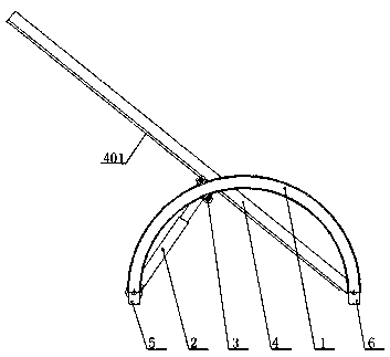
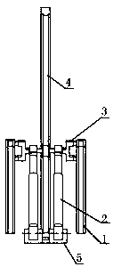
[0034] figure 2 and image 3 As shown, a constant force luffing mechanism includes a slide rail 1, a lifting cylinder 2, a sliding device 3 and a lifting arm 4. The slide rail is semicircular, and the slide rail is symmetrically fixed on the vehicle frame. The tail end of the oil cylinder is fixed on the frame through the hinge seat 5 of the oil cylinder, the working end of the lifting cylinder is rolled and supported on the two slide rails through the sliding device, and the tail end of the lifting arm is fixed on the frame through the hinge seat 6 of the lifting arm Above, the working end of the lifting arm is slidingly connected with the sliding device; during the lifting process of the lifting arm, the included angle between the lifting arm and the lifting cylinder is always a right angle;

[0035] like Figure 4 As shown, the structure of the sliding device 3 is as follows: comprising a roller bracket 301, the roller bracket is hinged with the working end of the liftin...


PUM


Abstract

A constant force amplitude changing mechanism comprises sliding rails, a lifting oil cylinder, a sliding device and a lifting arm. The sliding rails are semicircular, the sliding rails are symmetrically arranged on a vehicle frame, the tail end of the lifting oil cylinder is hinged to the vehicle frame, the working end of the lifting oil cylinder is supported on the two sliding rails through a siding device in a rolling mode, the tail end of the lifting arm is hinged to the vehicle frame, and the working end of the lifting arm is in sliding connection with the sliding device. In the ascendingor descending process of the lifting arm, the included angle between the lifting arm and the lifting oil cylinder is always a right angle, so that the lifting force of the oil cylinder is constant, the pressure intensity of an amplitude changing hydraulic system is constant, the using performance of the hydraulic system can be improved, and the service life of the system is effectively prolonged.

Description

technical field [0001] The invention relates to the field of the luffing mechanism of the main boom of a crane or the main boom of a concrete pump truck, in particular to a constant force luffing mechanism. [0002] It can also be used for dump truck hopper lifting mechanism and cab turning mechanism through reasonable improvement. In terms of layout space, it is especially suitable for large lifting equipment and concrete pumping equipment. Background technique [0003] The jib luffing mechanism of large-scale hoisting machinery and pumping machinery at home and abroad generally adopts hydraulic lifting mechanism. The advantage of the hydraulic system is that it has a strong bearing capacity, but due to the viscosity of the oil, there is a certain damping in the process of the hydraulic system transmitting force, which causes the system to heat up. When the heat is severe, the viscosity of the oil will decrease, and the carrying capacity of the system will drop significant...

Claims


Application Information

Patent Timeline
Patent Type & Authority Applications(China)
IPC IPC(8): B66C23/82
Inventor 付江华
Owner HUBEI DAYUN AUTOMOBILE
Learn More