Spark ignition internal combustion engine having intake valves with variable actuation and delayed closure

a technology of internal combustion engine and variable actuation, which is applied in the direction of machines/engines, non-mechanical valves, electrical control, etc., can solve the problems of large portion of the crossing of the intake and exhaust phases, unfavorable engine performance, and ineffective first part of the cam profile, so as to reduce the performance of the engine and increase the pollutant emissions , the effect of high backflow of air

Active Publication Date: 2015-12-01
CENT RICERCHE FIAT SCPA
View PDF9 Cites 0 Cited by
  • Summary
  • Abstract
  • Description
  • Claims
  • Application Information

AI Technical Summary

Benefits of technology

[0054]in that the aforementioned electronic control means are configured for controlling the aforesaid solenoid valve so that said boot portion with substantially constant lift will be reduced in duration by opening the solenoid valve when it is required to operate with a shorter closure delay of the intake valves.
[0058]It should in particular be noted that the profile of the control cam of the intake valve according to the aforesaid second embodiment of the invention, if combined to a traditional valve control, would give rise to serious drawbacks in operation of the engine. In fact, on account of the high backflow of air in the intake conduit, which would always be present to its highest extent, difficulties at engine start would be generated, as well as a drastic reduction of the performance of the engine and an unacceptable increase of the pollutant emissions at the exhaust. The combination of a cam having the profile defined above with the variable-valve-actuation system also defined above makes possible a modulation from zero to a maximum of the duration in time of the aforesaid boot with constant lift in the cycle of opening of the intake valve, subsequent to bottom dead centre.

Problems solved by technology

Once again in the case of the aforesaid application, at high engine r.p.m. the electronic control means of the solenoid valve are designed to keep the solenoid valve open in the phase preceding TDC, in such a way that the first part of the cam profile becomes ineffective and the intake valve remains closed substantially up to TDC.
At such high r.p.m., in fact, an ample portion of crossing of the intake and exhaust phases is unfavourable to the performance of the engine.
It is evident that the rich air-fuel ratio typical of operation at high loads does not make it possible to work with relative air-fuel ratio equal to 1, nor does the delayed ignition timing enable meeting one of the two conditions referred to above (whether MBF50 or pressure peak).

Method used


Image

  • Spark ignition internal combustion engine having intake valves with variable actuation and delayed closure
  • Spark ignition internal combustion engine having intake valves with variable actuation and delayed closure
  • Spark ignition internal combustion engine having intake valves with variable actuation and delayed closure

Examples


Embodiment Construction

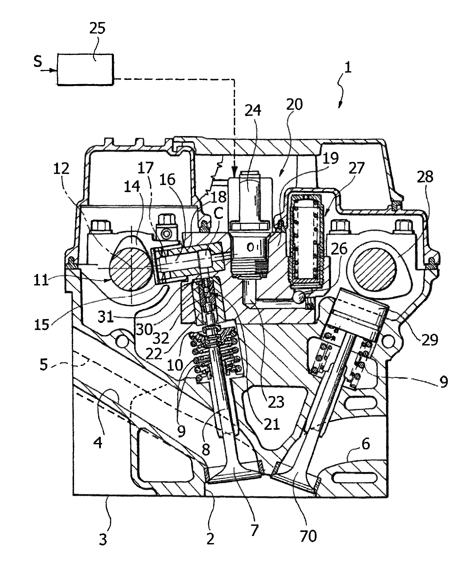
[0065]With reference to FIG. 3, in a preferred embodiment of the invention, intended to be applied on a spark-ignition engine, in particular a supercharged and preferably gasoline engine, the control cams of the intake valves have the profile indicated schematically in FIG. 3 (with reference to a clockwise direction of rotation of the camshaft) so as to generate a lift profile of the intake valves of the type illustrated in FIG. 4. In this figure, the profile has been illustrated with reference to a clockwise direction of rotation of the cam.

[0066]According to the aforesaid embodiment, the cam comprises a first portion of profile C1 that determines the lift of the intake valve and has a boot portion C2, with substantially constant lift, in the final part of the lift cycle of the valve, so as to cause a closure of the intake valves with considerable delay with respect to the bottom dead centre (BDC) of the piston of the respective cylinder.

[0067]In this way, during rising of the pist...


PUM


Abstract

A spark-ignition supercharged internal-combustion gasoline engine is equipped with a system for variable actuation of the intake valves including a pressurized fluid chamber set between intake valve and a respective control cam, and an electrically actuated valve, the opening of which vents the pressure chamber so as to cause rapid closing of the valve, as a result of the respective elastic return means, even when the respective cam would tend to keep the valve open. The variable-valve-actuation system is used in combination with control cams of the intake valves shaped in such a way as to generate an intake valve lift profile including a boot portion with substantially constant lift. The boot portion is provided in the final part of the opening cycle of the intake valve, after bottom dead center.

Description

CROSS REFERENCE TO RELATED APPLICATIONS[0001]This application claims priority from European patent application No. 13168369.0, filed on May 17, 2013, the entire disclosure of which is incorporated herein by reference.FIELD OF THE INVENTION[0002]The present invention relates to multi-cylinder internal-combustion engines, of the type comprising:[0003]at least one intake valve and at least one exhaust valve for each cylinder, each provided with respective elastic return means which bias the valve into a closed position, for controlling respective intake and exhaust conduits,[0004]at least one camshaft, for actuating the intake valves and the exhaust valves of the engine cylinders by means of respective tappets,[0005]wherein at least each intake valve has a variable actuation, being governed by the respective tappet, against the action of the aforesaid elastic return means, by interposition of hydraulic means including a pressurized fluid chamber, facing which is a pumping piston connec...

Claims


Application Information

Patent Timeline
Patent Type & Authority Patents(United States)
IPC IPC(8): F01L13/00F01L9/02F02D43/00F02D15/04F02D13/02F01L9/14
CPCF01L13/0015F01L9/025F02D15/04F02D43/00F02D13/0226F01L2013/0089Y02T10/12F01L9/14
Inventor BOREAN, FABIOSTROPPIANA, ANDREALUISI, SABINOVATTANEO, FRANCESCO
Owner CENT RICERCHE FIAT SCPA
Why Eureka
Try Eureka