Cross flow type fan wing device

A cross-flow fan and cross-flow technology, used in transportation and packaging, aircraft, motor vehicles, etc., can solve the problems of reducing aerodynamic efficiency, fan wing lift fluctuation, device vibration, etc., to reduce fluctuation and vibration, improve assembly efficiency, The effect of improving aerodynamic efficiency

Pending Publication Date: 2018-03-23
NANJING UNIV OF AERONAUTICS & ASTRONAUTICS
View PDF1 Cites 1 Cited by
  • Summary
  • Abstract
  • Description
  • Claims
  • Application Information

AI Technical Summary

Problems solved by technology

[0006] 1. The intermediate rotating shaft is also a transmission shaft, and it is easy to deform when the torque transmission is too long, which will cause greater noise and vibration when the speed increases
[0007] 2. When the fan blade rotates, since the transmission shaft is in the center of the fan blade, it will affect the eccentric vortex generated inside the fan blade, which will reduce the lift force and reduce the aerodynamic efficiency
[0008] 3. The blades of the currently used cross-flow fan blades are arranged parallel to each other around the drive shaft. Every time a blade turns to the back end of the concave table and enters the arc and turns to the front end of the concave table when the blade leaves the arc, the fan wing will The lift will fluctuate and change periodically, which not only brings fluctuations in the lift value, but also brings vibrations to the entire device, which is not conducive to the normal operation and use of the aircraft.
[0009] 4. When the fan wing is applied to the wing or rotor, it will be deformed due to the bending moment generated by the lift force from the root to the tip of the wing or rotor. big adverse effect
[0010] 5. When the fan wing is applied to the wing, the lift and thrust cannot be decoupled, and the lift or thrust cannot be adjusted independently, which will affect the control effect and increase the difficulty of control

Method used


Image

  • Cross flow type fan wing device
  • Cross flow type fan wing device
  • Cross flow type fan wing device

Examples


Embodiment Construction

[0051] The present invention will be further described in detail below in conjunction with the accompanying drawings and specific preferred embodiments.

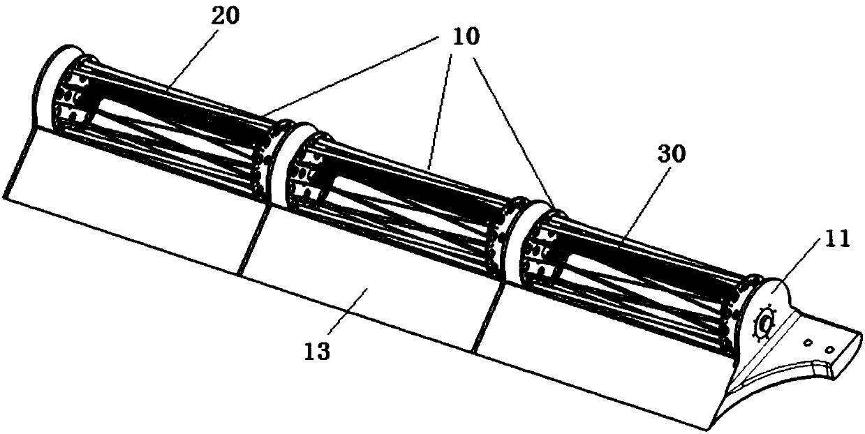
[0052] Such as figure 1 As shown, a cross-flow fan blade device includes several fan blade segments 10 connected in series and a cross-flow fan 20 that is mathematically equivalent to the fan blade segments, and two adjacent fan blade segments are fixedly connected.

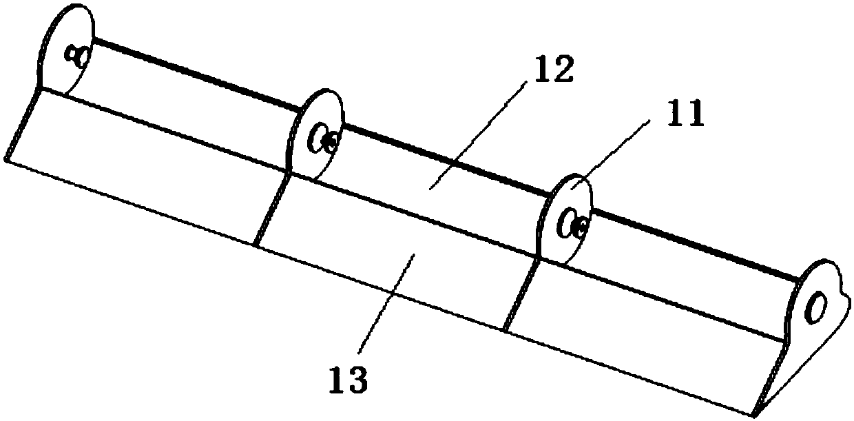
[0053] Such as image 3 As shown, each fan wing segment includes a support plate 11, an aerodynamic upper surface and a lower surface, the front of each fan wing segment forms a leading edge, and the rear of each fan wing segment Form the trailing edge.

[0054] The support plate 11 is preferably arranged on one end surface or both end surfaces of each fan wing segment, when the support plate is arranged on one end surface of each fan wing segment, such as image 3 As shown, two adjacent fan wing segments share a support plate.

[0055] When the support pla...


PUM


Abstract

A cross flow type fan wing device comprises a plurality of fan wing sections and a plurality of cross flow fans. Each cross flow fan comprises a cross flow fan body and a manipulating device. Each cross flow fan body comprises an end plate, a plurality of fan blades and an eccentric vortex cavity. Each manipulating device is arranged in the eccentric vortex cavity of each cross flow fan body, andcomprises a steering engine and a control surface body. The steering engines are arranged on the two sides of the control surface bodies, and each steering engine comprises a horizontal connection rod. One ends of the horizontal connection rods are fixedly connected with the steering engines, and the other ends of the horizontal connection rods are connected with the fan wing sections after penetrating out of the end plates. Under driving of the steering engines, the control surface bodies can move up and down and rotate in the eccentric vortex cavities. The cross flow type fan wing device canachieve decoupling control of the magnitude of lifting force or thrust of the cross flow fan wing. When the manipulating devices move towards the axes of the cross flow fan bodies, the thrust is increased while the lifting force is not changed basically. When the control surface bodies rotate, and the angle of attack is changed accordingly, the lifting force is decreased along with increasing ofthe angle of attack, and the thrust is not changed basically.

Description

technical field [0001] The invention relates to a general aviation device, in particular to a cross-flow fan wing device. Background technique [0002] The cross-flow fan wing is a new type of device that generates aerodynamic lift. It uses the rotating fan in front of the airfoil to generate vortex lift and thrust for flight. It has the advantages of good low-speed performance, large load, and no stall at large angles of attack. and the attention of researchers. [0003] The lift generated by the fan wing is composed of two parts: one is that when the fan rotates, the flow velocity on the upper and lower surfaces of the rear half of the wing is different, resulting in a pressure difference between the upper and lower surfaces of the wing, forming the lift of the wing. The other part is that when the fan rotates, a strong eccentric vortex is generated inside the fan, resulting in a strong eccentric vortex low-pressure area, which causes a large pressure difference between t...

Claims


Application Information

Patent Timeline
IPC IPC(8): B64C39/00
CPCB64C39/005
Inventor 朱清华曾嘉楠申镇朱振华招启军徐起
Owner NANJING UNIV OF AERONAUTICS & ASTRONAUTICS
Why Eureka
Try Eureka