
Static-state light reflection micro-thermal imaging method and device and terminal equipment

A technology of microscopic thermal imaging and light reflection, which is applied in the directions of measuring devices, optical radiation measurement, radiation pyrometry, etc.

Active Publication Date: 2019-05-28
THE 13TH RES INST OF CHINA ELECTRONICS TECH GRP CORP
View PDF7 Cites 9 Cited by
  • Summary
  • Abstract
  • Description
  • Claims
  • Application Information

AI Technical Summary

Problems solved by technology

[0004] In view of this, the embodiment of the present invention provides a static light reflection microscopic thermal imaging method, device and terminal equipment to solve the problem that the existing camera-based thermal imaging technology needs to modulate the temperature of the measured target

Method used


Image

  • Static-state light reflection micro-thermal imaging method and device and terminal equipment
  • Static-state light reflection micro-thermal imaging method and device and terminal equipment
  • Static-state light reflection micro-thermal imaging method and device and terminal equipment

Examples


Embodiment Construction

[0032] In the following description, specific details such as specific system structures and technologies are presented for the purpose of illustration rather than limitation, so as to thoroughly understand the embodiments of the present invention. It will be apparent, however, to one skilled in the art that the invention may be practiced in other embodiments without these specific details. In other instances, detailed descriptions of well-known systems, devices, circuits, and methods are omitted so as not to obscure the description of the present invention with unnecessary detail.

[0033] In order to illustrate the technical solutions of the present invention, specific examples are used below to illustrate.

[0034] The basic feature of photothermal reflection phenomenon is that the reflectivity of the object will change with the temperature of the object. In the prior art, the change of reflectivity with temperature can be considered linear, so it can be characterized by a ...


PUM


Abstract

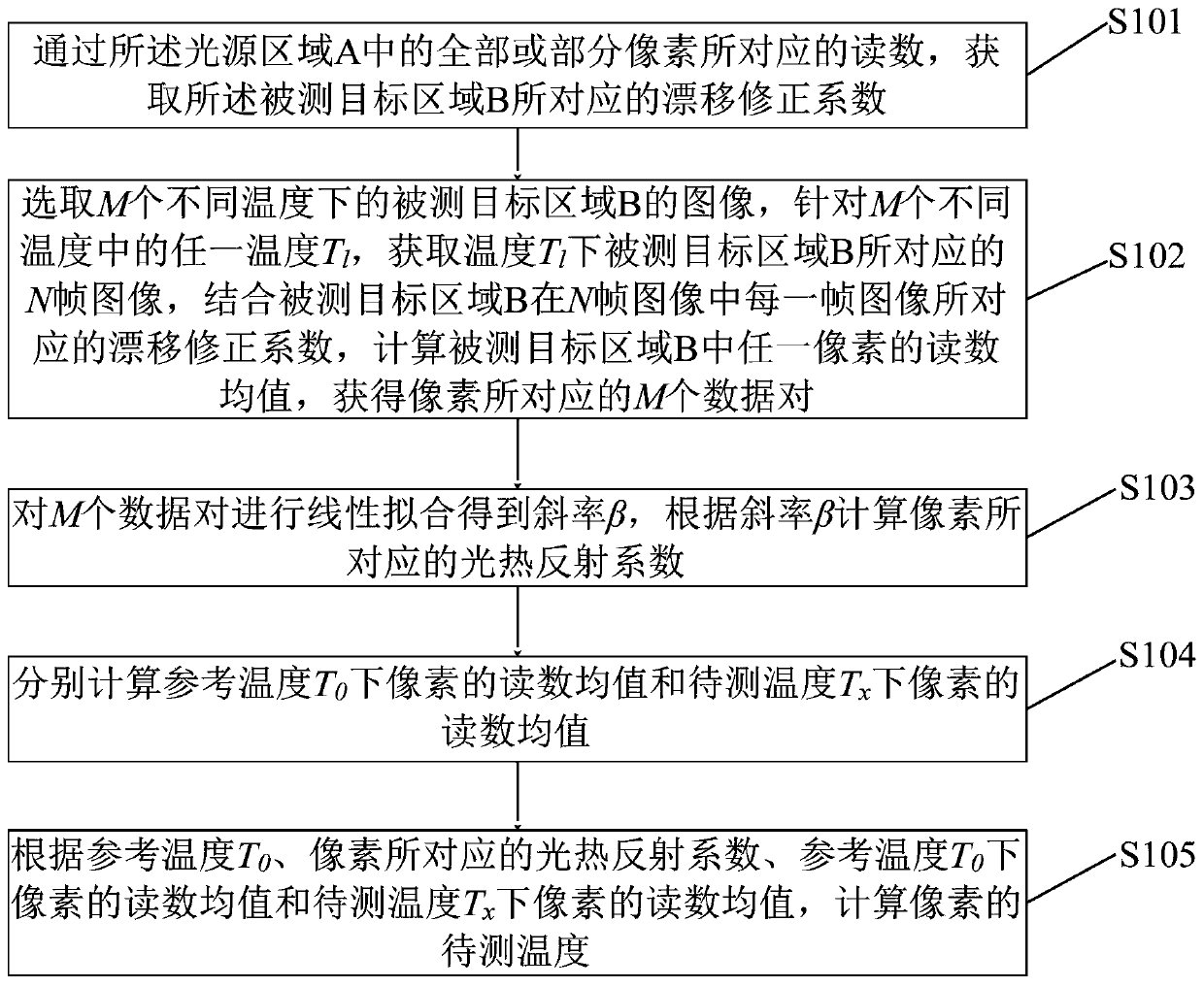
The invention provides a static-state light reflection micro-thermal imaging method and device and terminal equipment. The method comprises the steps that images of a measured light source area A anda measured target area B are acquired at the same time, and through pixel reading of the light source area A, a drifting correction coefficient of the measured target area B is acquired; N frames of images of the measured target area B at all temperatures are acquired at M different temperatures, a reading mean value, shown in the description, of any pixel bk in the measured target area B is calculated, and M data pairs corresponding to bk are acquired; linear fitting is conducted for obtaining a slope beta, and a photo-thermal reflection coefficient CTR(bk) corresponding to bk is calculated according to beta; a reading mean value, shown in the description, of bk at a reference temperature T0 and a reading mean value, shown in the description, of bk at a to-be-measured temperature Tx are calculated separately; according to T0, CTR(bk) and the two values shown in the description, the to-be-measured temperature Tx(bk) of bk is calculated. The problem is solved that based on a thermal imaging technology of a camera, the temperature of a measured object needs to be modulated.

Description

technical field [0001] The invention belongs to the technical field of temperature detection and microscopic imaging, and in particular relates to a static light reflection microscopic thermal imaging method, device and terminal equipment. Background technique [0002] Photothermal reflection temperature measurement technology is a non-contact temperature measurement technology based on the phenomenon of thermoreflectance. The basic feature of photothermal reflection phenomenon is that the reflectivity of an object will change with the temperature of the object. Microscopic thermal imaging technology based on the principle of light reflection is often used for temperature detection of microelectronics and optoelectronic devices. Laser and VCSEL (Vertical Cavity Surface Emitting Laser, Vertical Cavity Surface Emitting Laser) emission surface damage, etc. [0003] Existing thermal imaging technologies based on the principle of light reflection can be divided into two categor...

Claims


Application Information

Patent Timeline
Patent Type & Authority Applications(China)
IPC IPC(8): G01J5/00
Inventor 刘岩梁法国翟玉卫赵琳丁晨
Owner THE 13TH RES INST OF CHINA ELECTRONICS TECH GRP CORP
Learn More