Condition monitoring sensor system and method for monitoring condition of system

A technology for monitoring sensors and conditions, applied in the field of monitoring system conditions and condition monitoring sensor systems

Active Publication Date: 2019-05-28
AB SKF
View PDF26 Cites 0 Cited by
  • Summary
  • Abstract
  • Description
  • Claims
  • Application Information

AI Technical Summary

Problems solved by technology

In some cases, the housing containing the system electronics is permanently sealed; there is no ability to power cycle the condition monitoring system or reprogram it using wired methods

Method used


Image

  • Condition monitoring sensor system and method for monitoring condition of system
  • Condition monitoring sensor system and method for monitoring condition of system
  • Condition monitoring sensor system and method for monitoring condition of system

Examples


Embodiment Construction

[0022] Various examples will now be described more fully with reference to the accompanying drawings in which some examples are shown. In the drawings, the thicknesses of lines, layers and / or regions may be exaggerated ( / magnified) for clarity.

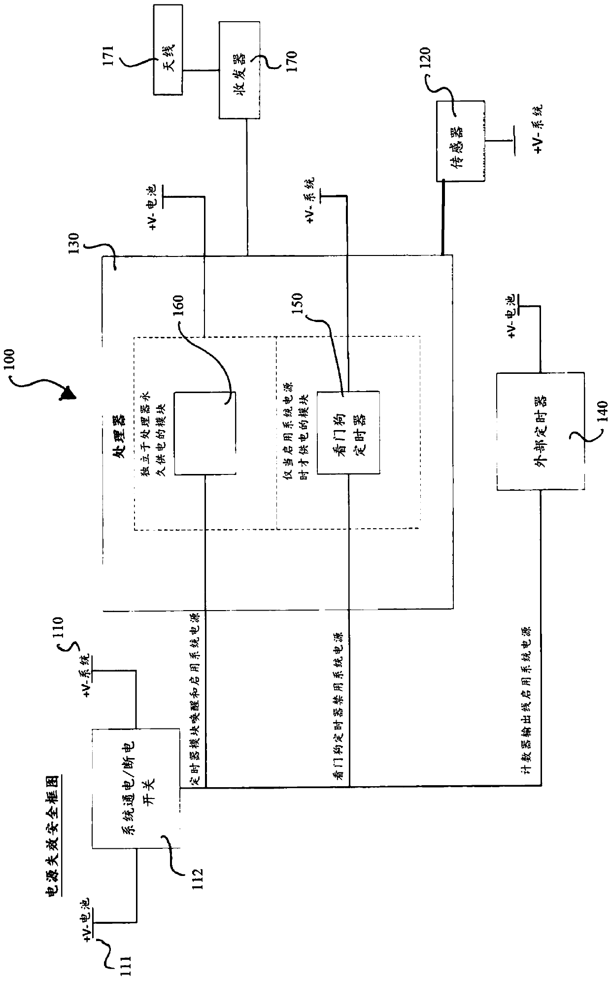
[0023] figure 1 A block diagram of a condition ( / status) monitoring system 100 is shown. The condition monitoring system 100 includes a power supply (V-system) 110 , a condition monitoring sensor 120 , a processor 130 , a power-on timer 140 and a watchdog timer 150 . System 100 may also include a real-time clock (RTC) 160, which serves as figure 1 The example shown uses the primary wake-up source.

[0024] The power supply 110 is connected to various system components through a system power switch 112 . The power source 110 may be a limited power source, such as a battery or a harvester, or it may be connected to a substantially larger power source, such as that of the device to be monitored. The system power switch 112 may compr...


PUM


Abstract

A condition monitoring sensor system has a power supply; a condition monitoring sensor; a processor; a permanently powered power-on timer; and a watchdog timer. The permanently powered power-on timeris set for a first predetermined duration and is configured to wake the processor by connecting the processor to the power supply if the power-on timer elapses. Upon waking up, the processor is configured to reset the power-on timer to the first predetermined duration and is configured to control at least the condition monitoring sensor. The condition monitoring sensor may take condition monitoring data. Upon waking up, the processor is configured to set the watchdog timer for a second predetermined duration. The watchdog timer is powered via the power supply, which forces the processor and the watchdog timer to enter a sleep mode by disconnecting the processor and the watchdog timer from the power supply if the watchdog timer elapses.

Description

technical field [0001] The present disclosure relates to condition monitoring devices, and more particularly to condition monitoring sensor systems and methods for monitoring the condition of (the) systems. Background technique [0002] A condition monitoring system allows the condition of the system to be monitored without manual inspection. These systems are especially important in remote areas or areas where access is difficult or dangerous, such as axles and / or bearings of railway ( / track) systems, especially in active operation. In these situations, a remote wireless condition monitoring system can be used. [0003] The remote wireless condition monitoring system may be powered by a battery pack or a limited ( / limited) capacity power source such as a harvester. One consideration in the design of wireless condition monitoring systems is the time between maintenance, which is often determined by their battery life. Therefore, power management is an important factor in ...

Claims


Application Information

Patent Timeline
IPC IPC(8): G01M13/045G01D21/02
CPCB61L15/0081G06F11/0757G06F11/3013G06F11/3089G06F11/3055G06F11/1441G06F11/0721G08B29/02G06F11/3003
Inventor 朱利安·弗兰基蒂马克·罗德斯
Owner AB SKF
Why Eureka
Try Eureka