
Method and system for automatically detecting backlight of panel

A technology of automatic detection and detection algorithm, applied in the direction of optics, nonlinear optics, instruments, etc., can solve the problems of low detection efficiency and low accuracy, and achieve the effect of improving accuracy, ensuring accuracy, and improving accuracy

Inactive Publication Date: 2019-05-28
WUHAN JINGLI ELECTRONICS TECH +1
View PDF6 Cites 3 Cited by
  • Summary
  • Abstract
  • Description
  • Claims
  • Application Information

AI Technical Summary

Problems solved by technology

[0006] In view of this, an embodiment of the present invention provides a method and system for automatically detecting panel backlight, to solve or at least partially solve the technical problems of low detection efficiency and low accuracy in the prior art

Method used


Image

  • Method and system for automatically detecting backlight of panel
  • Method and system for automatically detecting backlight of panel
  • Method and system for automatically detecting backlight of panel

Examples


Embodiment 1

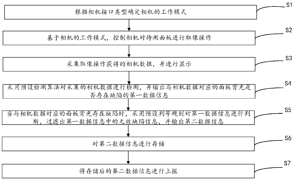
[0058] This embodiment provides a method for automatically detecting panel backlight, please refer to figure 1 , the method includes:

[0059] First execute step S1: determine the working mode of the camera according to the type of the camera interface.

[0060]Specifically, the camera interface is divided into a USB interface, a network interface and an AOI hardware platform interface. In this embodiment, these three interfaces are supported. When the optical scheme is determined, the appropriate interface control method can be selected according to the camera type selected in the optical scheme, so that the cost can be minimized.

[0061] Then step S2 is executed: based on the working mode of the camera, the camera is controlled to perform an image capturing operation on the panel to be tested.

[0062] In one embodiment, controlling the camera to perform an image capturing operation of the panel to be tested includes:

[0063] By adjusting the angle and focal length of t...

Embodiment 2

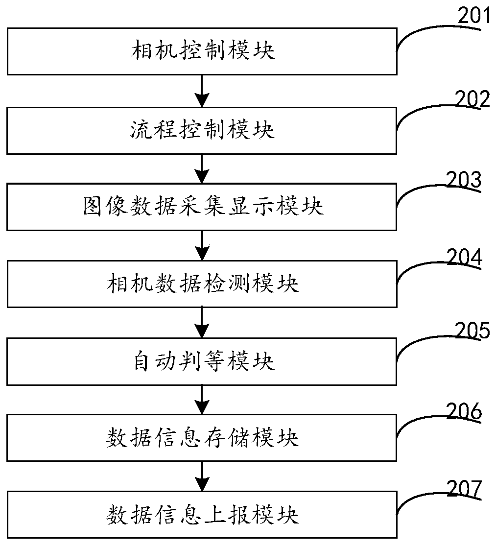
[0101] This embodiment provides a system for automatically detecting panel backlight, please refer to figure 2 , the system consists of:

[0102] A camera control module 201, configured to determine the working mode of the camera according to the type of the camera interface;

[0103] A process control module 202, configured to control the camera to perform an imaging operation on the panel to be tested based on the working mode of the camera;

[0104] The image data collection and display module 203 is used to collect and display the camera data obtained by the imaging operation;

[0105] The camera data detection module 204 is configured to detect the collected camera data by using a preset detection algorithm, and output the first data information of whether the panel backlight corresponding to the camera data is defective;

[0106] The automatic judgment module 205 is used for judging the first data information by using preset judgment rules when the panel backlight cor...


PUM


Abstract

The invention provides a method and system for automatically detecting backlight of a panel. The method comprises the steps of firstly, determining a working mode of a camera according to a camera interface type, and then controlling the camera to perform image acquisition operation on the panel to be detected on the basis of the working mode of the camera; collecting camera data acquired throughthe image acquisition operation and displaying the camera data; then, detecting the collected camera data by means of a preset detection algorithm and outputting first data information indicating whether the backlight, corresponding to the camera data, of the panel has defects or not; when the backlight, corresponding to the camera data, of the panel has defects, judging the first data informationby means of a preset judgment rule, filtering out invalid defect information in the first data information, and outputting second data information; storing the second data information; finally, reporting the stored second data information. The method and the system achieve the technical effects of improving the detection efficiency and increasing the accuracy rate.

Description

technical field [0001] The invention relates to the technical field of automatic optical detection, in particular to a method and system for automatically detecting panel backlight. Background technique [0002] With the development of display technology, liquid crystal displays (Liquid Crystal Display, LCD) and other flat display devices are widely used in mobile phones, televisions, personal digital assistants, digital cameras due to their advantages of high image quality, power saving and wide application range. In electronic products such as electronic products, it has become the mainstream of display devices. [0003] Most of the liquid crystal display devices currently on the market are backlight liquid crystal displays, which include a liquid crystal display panel and a backlight module. In order to detect the display effect of the display, it is necessary to detect the backlight of the display panel. [0004] During the process of implementing the present invention,...

Claims


Application Information

Patent Timeline
Patent Type & Authority Applications(China)
IPC IPC(8): G02F1/13
Inventor 杨阳欧昌东
Owner WUHAN JINGLI ELECTRONICS TECH
Learn More