Clamping method and clamp for thin-wall cylindrical part turning as well as processing device

A thin-walled cylinder and fixture technology, applied in the field of turning processing, can solve problems such as workpiece deformation and chattering accuracy, and achieve the effects of low manufacturing cost, low load and light weight

Active Publication Date: 2019-05-31
SHANDONG UNIV
View PDF8 Cites 6 Cited by
  • Summary
  • Abstract
  • Description
  • Claims
  • Application Information

AI Technical Summary

Problems solved by technology

[0003] The object of the present invention is to overcome the deficiencies of the above-mentioned prior art and provide a clamping method for turning thin-walled cylindrical parts, which avoids the accuracy problems caused by workpiece deformation and chatter caused by conventional clamping methods for thin-walled cylindrical parts

Method used


Image

  • Clamping method and clamp for thin-wall cylindrical part turning as well as processing device
  • Clamping method and clamp for thin-wall cylindrical part turning as well as processing device
  • Clamping method and clamp for thin-wall cylindrical part turning as well as processing device

Examples


Embodiment Construction

[0029] It should be pointed out that the following detailed description is exemplary and intended to provide further explanation to the present application. Unless defined otherwise, all technical and scientific terms used herein have the same meaning as commonly understood by one of ordinary skill in the art to which this application belongs.

[0030] It should be noted that the terminology used here is only for describing specific implementations, and is not intended to limit the exemplary implementations according to the present application. As used herein, unless the context clearly dictates otherwise, the singular is intended to include the plural, and it should also be understood that when the terms "comprising" and / or "comprising" are used in this specification, they mean There are features, steps, operations, means, components and / or combinations thereof.

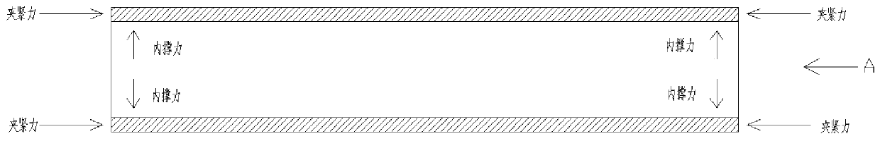
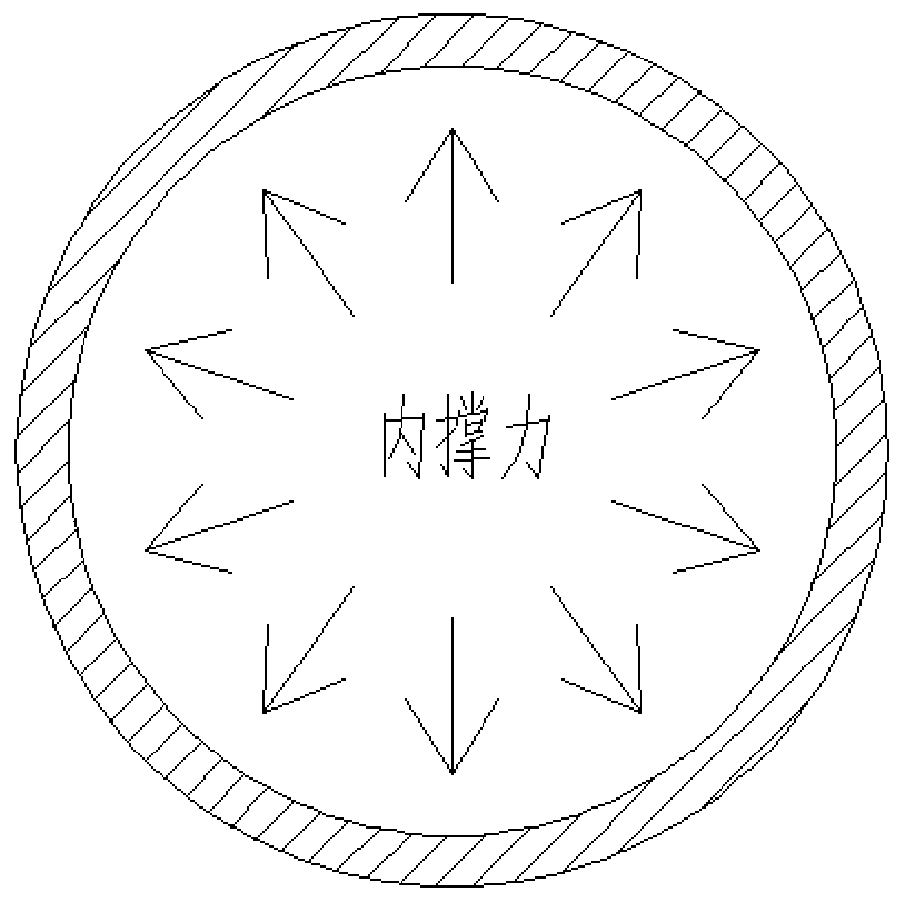
[0031] As introduced in the background technology, the existing clamping method for turning thin-walled cylindri...


PUM


Abstract

The invention relates to a clamping method and a clamp for thin-wall cylindrical part turning as well as a processing device. The clamp comprises a first supporting shaft and a second supporting shaft, wherein one end of the first supporting shaft and one end of the second supporting shaft are connected to a tightening mechanism; the tightening mechanism is used for applying inner supporting forceto the two ends of a thin-wall cylindrical part; a limiting structure is arranged on the tightening mechanism; and the limiting structure is used for limiting axial movement of the thin-wall cylindrical part. The clamping method and the clamp disclosed by the invention avoid the problem that a workpiece has clamping deformation and chattering, and improve processing precision.

Description

technical field [0001] The invention relates to the technical field of turning processing, in particular to a clamping method, a fixture and a processing device for turning a thin-walled cylindrical part. Background technique [0002] The existing processing methods and tooling for thin-walled cylindrical parts mainly include: first, the most common method is to add an elastic sleeve to the outer circle of the workpiece for radial clamping or clamping with a three-jaw chuck. This technology is easy to clamp the workpiece Deformation, reduced precision, and low production efficiency; the second is the one-piece shaft fixation, allowing the workpiece to be set on the shaft and fixed at both ends, and the middle is filled with rubber, paraffin and other media. Due to the heat generated by the processing engineering, the media will melt and the filling will be uneven. , so it is easy to cause the workpiece to flutter. The integrated solid shaft type makes the machine tool spind...

Claims


Application Information

Patent Timeline
Patent Type & Authority Applications(China)
IPC IPC(8): B23B31/40
CPCB23B31/404
Inventor 宋清华王小娟巫永琳刘战强陈龙
Owner SHANDONG UNIV
Why Eureka
Try Eureka