
Novel tin soldering gun

A new type of soldering technology, applied in the direction of tin feeding device, welding equipment, soldering iron, etc., can solve the problems of low safety and frequent replacement of solder wire, etc., and achieve the effect of improving safety and improving work efficiency

Inactive Publication Date: 2019-05-31
XIAN SINENG NETWORK SCI & TECH
View PDF0 Cites 1 Cited by
  • Summary
  • Abstract
  • Description
  • Claims
  • Application Information

AI Technical Summary

Problems solved by technology

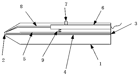
[0003] In order to solve the problem in the prior art that the solder wire and the electric soldering iron are used separately, the safety is too low, and the solder wire needs to be replaced frequently, the present invention provides a new type of solder gun, which is easy to use, safe and reliable, and does not require Advantages of frequent replacement of solder wire

Method used


Image

  • Novel tin soldering gun

Examples


Embodiment Construction

[0013] In order to further illustrate the purpose of improving the welding efficiency and safety of the welding wire in the present invention, the specific implementation, structural features and effects of the present invention will be described in detail below in conjunction with the accompanying drawings and examples.

[0014] In the description of the present invention, it should be understood that the orientation or positional relationship indicated by the terms "front", "rear", "upper", "lower", "inner", "outer" etc. Orientation or positional relationship is only for the convenience of describing the present invention and simplifying the description, and does not indicate or imply that the referred device or element must have a specific orientation, be constructed and operated in a specific orientation, and therefore cannot be construed as limiting the present invention

[0015] Such as figure 1 As shown, a new type of soldering gun includes a hollow tubular soldering gu...


PUM


Abstract

The invention belongs to the field of welding tools, in particular to a novel tin soldering gun. The tin soldering gun comprises a tin soldering gun body which adopts the shape of a hollow pipe and atin soldering gun head, wherein a wire inlet is formed in the center of the rear end of the tin soldering gun body, and the front end of the tin soldering gun body is connected with the tin solderinggun head; a circular tin solder wire cavity is arranged in the tin soldering gun body in the length direction of the tin soldering gun body; one end of the tin solder wire cavity communicates with thewire inlet and is fixedly arranged at the rear end of the tin soldering gun body, and the other end of the tin solder wire cavity is connected with the tin soldering gun head; a return plate and a flexible insulating column which are mutually parallel are sequentially arranged at the upper part of the tin solder wire cavity from bottom to top; one end of the return plate is connected with the rear end surface of the tin soldering gun body, and the other end of the return plate is hung in the air; a welding protrusion is arranged at the upper part of the flexible insulating column, and extendsout of the outer wall of the tin soldering gun body; an electric soldering iron is arranged at the front end of the flexible insulating column, and the rear end of the flexible insulating column is fixedly arranged at the rear end of the tin soldering gun body; and a return spring is arranged between the flexible insulating column and the return plate.

Description

technical field [0001] The invention belongs to the technical field of welding tools, and in particular relates to a novel solder gun. Background technique [0002] Soldering technology is an indispensable technical means for welding components, and a certain safety awareness is required during the use process. However, the current traditional soldering tools are very simple, and most of them use soldering tin and electric soldering iron separately, which is very inconvenient to operate, resulting in work Low efficiency; and currently some tools that use solder and electric soldering iron in combination, the wire feeding method is mostly front-end wire feeding, resulting in frequent wire feeding during use, and the electric soldering iron and solder wire are in contact regardless of whether they are working or not, which is extremely difficult. It is easy to bring potential safety hazards. Based on this, it is necessary to design a new type of solder gun with high efficiency...

Claims


Application Information

Patent Timeline
Patent Type & Authority Applications(China)
IPC IPC(8): B23K3/06B23K3/03
Inventor 孙圆媛
Owner XIAN SINENG NETWORK SCI & TECH
Learn More