Commercial vehicle frame assembly

A commercial vehicle and vehicle frame technology, applied to vehicle parts, substructure, transportation and packaging, etc., can solve the problems of increasing radiator area, limited width, radiator assembly width, etc., and achieve the goal of increasing cost Effect

Pending Publication Date: 2019-05-31
湖北三环汽车有限公司
View PDF0 Cites 1 Cited by
  • Summary
  • Abstract
  • Description
  • Claims
  • Application Information

AI Technical Summary

Problems solved by technology

[0002] The outer width of the existing frame assembly has been solidified by the front and rear suspensions and body mounts, resulting in the limitation of the width of the radiator assembly, and the area of ​​the radiator directly affects whether the vehicle can pass the water temperature test. The area of ​​the radiator is determined by Z The height difference in the direction is determined by the width in the Y direction, but the heat sink has been developed to the extreme in the Z direction, and it is no longer possible to increase the heat sink area by increasing the height difference in the Z direction
[0003] Although the current vehicle frame also uses widening the distance between the front ends of the two longitudinal beams to increase the installation width of the radiator assembly, the increased width of this method is limited, and the width of the radiator in the Y direction is still limited. The maximum horsepower of the matching engine is restricted

Method used


Image

  • Commercial vehicle frame assembly
  • Commercial vehicle frame assembly

Examples


Embodiment Construction

[0013] The technical solution of the present invention will be clearly and completely described below in conjunction with the accompanying drawings, but this embodiment should not be construed as limiting the present invention.

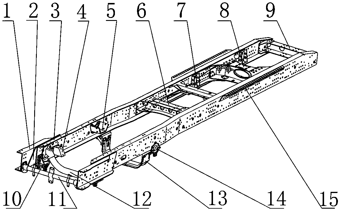
[0014] The present invention as Figure 1 to Figure 2 Shown:

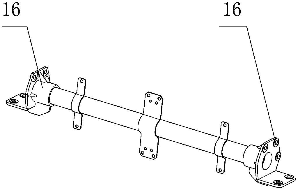
[0015] A commercial vehicle frame assembly, comprising left and right longitudinal beams 3, the cross-section of the left and right longitudinal beams 3 is U-shaped and the openings are arranged inwardly, and the front-end ventral sides of the left and right longitudinal beams 3 are fixed with a The left and right side beams 1 are extended from the front ends of the left and right longitudinal beams 3, and the two ends of the first beam assembly 11 are respectively installed under the front ends of the left and right side beams 1;

[0016] The cross-section of the left and right valgus 1 is a U-shaped structure and the opening is set outward, and is fixedly connected with the outside of t...


PUM


Abstract

The invention discloses a commercial vehicle frame assembly. The assembly comprises left and right longitudinal beams, the left and right longitudinal beams have U-shaped sections, openings are formedinwards, the left and right longitudinal beams are connected and integrated by a plurality of cross beams, left and right outer flanging beams extending to the front ends of the left and right longitudinal beams are fixed on the outer sides of the front end belly surfaces of the left and right longitudinal beams, and the two ends of a first cross beam assembly are respectively installed at the lower portions of the front ends of the left and right outer flanging beams; the cross sections of the left and right outer flanging beams are of U-shaped structures, openings are outwards formed, the left and right outer flanging beams are fixedly connected to the outer sides of the belly surfaces of the left and right longitudinal beams back to back, a cavity between the outer sides of the belly surfaces of the left and right outer flanging beams forms a heat dissipation device compartment, and the first cross beam assembly is connected to the lower aerofoil and the outer sides of the belly surfaces of the left and right outer flanging beams by mounting brackets at both ends. The assembly increases the design space of a heat dissipation device in the Y direction by widening the width of the vehicle frame heat dissipation device compartment without greatly increasing the cost so that the vehicle frame can be matched with an engine with more horsepower of a vehicle type of the same class.

Description

technical field [0001] The invention relates to the technical field of commercial vehicle components, in particular to a commercial vehicle frame assembly. Background technique [0002] The outer width of the existing frame assembly has been solidified by the front and rear suspensions and body mounts, resulting in the limitation of the width of the radiator assembly, and the area of ​​the radiator directly affects whether the vehicle can pass the water temperature test. The area of ​​the radiator is determined by Z The height difference in the direction is determined by the width in the Y direction, but the heat sink has been developed to the extreme in the Z direction, and it is no longer possible to increase the heat sink area by increasing the height difference in the Z direction. [0003] Although the current vehicle frame also uses widening the distance between the front ends of the two longitudinal beams to increase the installation width of the radiator assembly, the...

Claims


Application Information

Patent Timeline
Patent Type & Authority Applications(China)
IPC IPC(8): B62D21/02B62D21/09
Inventor 许丽娟梁伟赵永振燕飞李阳雪宋显义李豪代飞胡健于远超王伟龙侯国栋冯广慧梁智发曹磊周文明陈双峰喻伟业王宇海刘富祥周椿甘宇陈文静叶鸿志李伟
Owner 湖北三环汽车有限公司
Why Eureka
Try Eureka