Liner assembly and assembling method thereof, shock absorber and vehicle
A shock absorber and bushing technology, which is applied in the direction of springs/shock absorbers, springs made of plastic materials, mechanical equipment, etc., can solve the problems of small radial stiffness of bushings and insufficient space for stiffness adjustment, and achieve reduction Effects of weight, increased rigidity, and improved assembly efficiency
- Summary
- Abstract
- Description
- Claims
- Application Information
AI Technical Summary
Problems solved by technology
Method used
Image
Examples
Embodiment 1
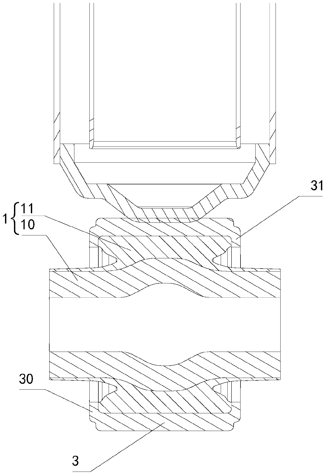
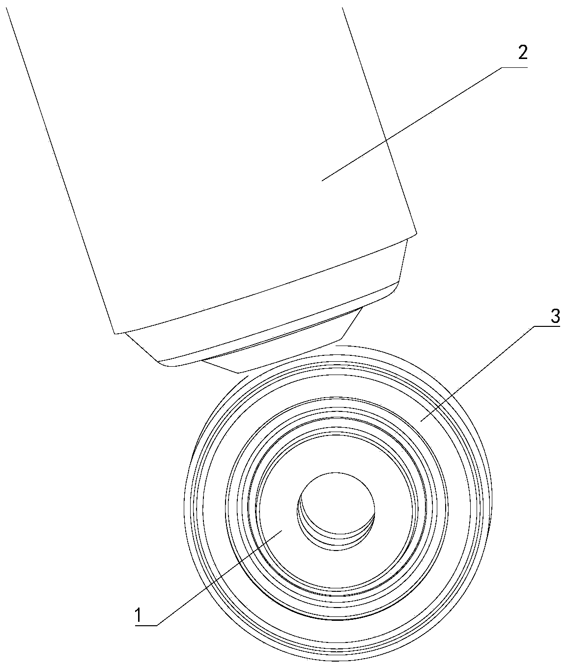
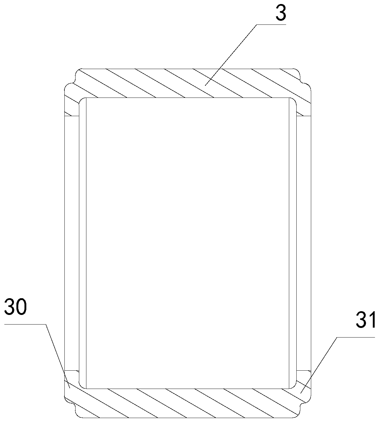
[0047] see Figure 1-Figure 5 As shown, this embodiment provides a bushing assembly; figure 1 A structural schematic diagram of the bushing assembly provided in this embodiment, figure 2 Another structural schematic diagram of the bushing assembly provided in this embodiment, wherein, figure 1 and figure 2 is the state where the bushing assembly is connected to the bottom of the shock absorber body, where figure 1 is a sectional view of the bushing assembly; image 3 A structural schematic diagram of the fixed ring of the bushing assembly provided in this embodiment, Figure 4 Another schematic diagram of the structure of the fixed ring of the bushing assembly provided in this embodiment, wherein, image 3 In order to show the structure more clearly, a cross-sectional view is used; Figure 5 A schematic structural view of the bushing assembly of the bushing assembly provided by Embodiment 1 of the present application is shown.
[0048] The bushing assembly provided in...
Embodiment 2
[0069] Embodiment 2 provides an assembly method of a bushing assembly, which is used to assemble the bushing assembly described in Embodiment 1. The technical features of the bushing assembly disclosed in Embodiment 1 are also applicable to this embodiment. Example 1 The technical features of the disclosed bushing assembly will not be described repeatedly.
[0070] The assembly method of the bushing assembly provided in this embodiment includes the following steps:
[0071] Step S100, forming a circumferential protrusion on the outer surface of the straight pipe to obtain a sleeve;
[0072] Step S102, sleeve the rubber bushing body on the outer surface of the casing, so that a circumferential groove matching the circumferential protrusion is formed on the rubber bushing body, and the casing is fixedly connected with the rubber bushing body to form a bushing assembly;
[0073] Step S103, pressing the bush assembly into the fixing ring.
[0074] The bushing assembly is assembl...
Embodiment 3
[0085] Embodiment 3 provides a shock absorber, including the bushing assembly in Embodiment 1. The technical features of the bushing assembly disclosed in Embodiment 1 are also applicable to this embodiment. The bushing assembly disclosed in Embodiment 1 The technical characteristics of the assembly will not be described repeatedly.
[0086] The shock absorber provided in this embodiment includes a bushing assembly and a shock absorber body, and the fixing ring of the bushing assembly is connected to the bottom of the shock absorber body. By connecting the bushing assembly below the shock absorber body, secondary shock absorption for the shock absorber body can be achieved through the bushing assembly.
[0087] The shock absorber in this embodiment has the advantages of the bushing assembly in the first embodiment, and the advantages of the bushing assembly disclosed in the first embodiment will not be repeated here.
PUM
 Abstract
Description
Claims
Application Information
 - R&D
- Intellectual Property
- Life Sciences
- Materials
- Tech Scout
- Unparalleled Data Quality
- Higher Quality Content
- 60% Fewer Hallucinations
Browse by: Latest US Patents, China's latest patents, Technical Efficacy Thesaurus, Application Domain, Technology Topic, Popular Technical Reports.
© 2025 PatSnap. All rights reserved.Legal|Privacy policy|Modern Slavery Act Transparency Statement|Sitemap|About US| Contact US: help@patsnap.com


