Method and system for locating grounding fault of power transmission line

A technology for transmission lines and ground faults, applied in the field of power systems, can solve the problems of difficult to guarantee reliability, complex system structure, and large differences in line parameters, and achieve the effect of convenient, timely and rapid finding.

Inactive Publication Date: 2019-05-31
云南电网有限责任公司保山供电局
View PDF4 Cites 7 Cited by
  • Summary
  • Abstract
  • Description
  • Claims
  • Application Information

AI Technical Summary

Problems solved by technology

This kind of anti-misoperation device has a certain effect, but there are two problems: one is that it can only identify the grounding switch, but it can't do anything to the temporarily overlapped grounding wire; the other is that this type of device depends on the correct detection of the status of the switch device and smooth communication channels, the system structure is relatively complex, and reliability is difficult to guarantee
This kind of anti-misoperation device has a certain effect, but there are two problems: one is that it can only identify

Method used


Image

  • Method and system for locating grounding fault of power transmission line
  • Method and system for locating grounding fault of power transmission line

Examples


Embodiment 1

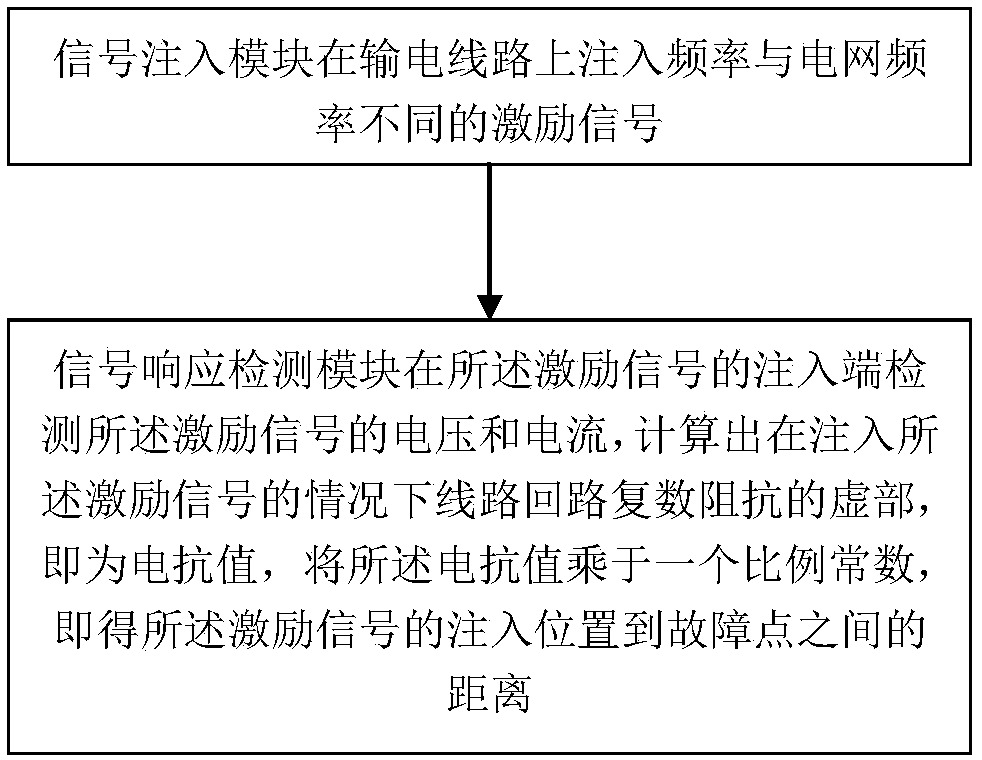
[0035] see figure 2 , the present embodiment provides a method for locating a transmission line ground fault, comprising the following steps:

[0036] The signal injection module injects an excitation signal with a frequency different from that of the power grid on the transmission line;

[0037] The signal response detection module detects the voltage and current of the excitation signal at the injection end of the excitation signal, and calculates the imaginary part of the complex impedance of the line loop when the excitation signal is injected, which is the reactance value, and the reactance The value is multiplied by a proportional constant to obtain the distance between the injection position of the excitation signal and the fault point.

[0038] The response of the transmission line under the action of the excitation signal can obviously reflect whether there is a short circuit in the line. The signal injection module can withstand induced voltage. The signal response...

Embodiment 2

[0049] This embodiment provides a positioning system for a ground fault of a transmission line, which includes a signal injection module and a signal response detection module. The signal injection module is used to inject an excitation signal with a frequency different from that of the power grid on the transmission line; the signal response detection module is used to detect the voltage and current of the excitation signal at the injection end of the excitation signal, and calculate the In the case of injecting the excitation signal, the imaginary part of the complex impedance of the line loop is the reactance value, and multiplying the reactance value by a proportional constant can obtain the distance between the injection position of the excitation signal and the fault point.

[0050] The operation method and working principle of the transmission line ground fault locating system are the same as the method described in Embodiment 1, so details will not be repeated here.


PUM


Abstract

The invention discloses a method for locating a grounding fault of a power transmission line. The method comprises the following steps that a signal injection module injects an excitation signal withthe frequency different from that of a power grid into the power transmission line; a signal response detection module detects the voltage and the current of the excitation signal at the injection endof the excitation signal, and calculates an imaginary part of the complex impedance of a line loop under the condition that the excitation signal is injected, i.e., a reactance value, and multipliesthe reactance value by a proportional constant to obtain the distance between the injection position of the excitation signal and a fault point. Therefore, the method can be used for directly detecting whether the power transmission line is grounded or not so as to judge whether a closing condition is met or not, and can also be used for judging the electrical distance of a grounding point when the grounding condition is met, so that the grounding point can be conveniently and quickly found in time and eliminated. The invention also discloses a system for locating the grounding fault of the power transmission line.

Description

technical field [0001] The invention relates to the field of power systems, in particular to a method and system for locating a ground fault of a power transmission line. Background technique [0002] The hanging ground wire is a safety barrier to protect the maintenance personnel and the lifeline of the electric power employees, which can prevent the harm to the human body caused by a sudden call. However, in actual work, due to the frequent use of the ground wire and the seemingly simple operation, it is easy to paralyze people's minds, and its importance is often overlooked by people. Incorrect use often occurs, which reduces or even loses the safety of the ground wire. The protective effect must be paid enough attention to. During line maintenance, how to ensure that the grounding wire is effectively connected, in addition to following the safety regulations for correct operation, it is also hoped that there will be obvious and intuitive means of judging the connection ...

Claims


Application Information

Patent Timeline
IPC IPC(8): G01R31/02G01R31/08
CPCY04S10/52
Inventor 张晓龙王继承周东伟宫贺余晶晶熊鸿楗李国武陈振宇蒋绍康蒋正虎杨尚玉李延龙王华楠陆雪峰寸杰宏
Owner 云南电网有限责任公司保山供电局
Why Eureka
Try Eureka