Aluminum alloy cabling rack and application method

A cable rack and aluminum alloy technology, applied in the direction of optical fiber/cable installation, etc., can solve the problems of narrow application range, affecting work efficiency, troubles, etc., and achieve the effects of strong adjustability, improved installation convenience, and flexible structure adjustment

Pending Publication Date: 2019-05-31
HEBEI HONGYU COMM EQUIP
View PDF1 Cites 0 Cited by
  • Summary
  • Abstract
  • Description
  • Claims
  • Application Information

AI Technical Summary

Problems solved by technology

[0002] At present, there are many kinds of optical cable racks, each with its own characteristics. Some cable racks are welded into a ladder-shaped frame body, and the frame body is installed on the top of the room through hanging ribs, and the optical cable is fixed on the top of the frame body through cable ties. For the wiring layout of optical cables, most of the existing wiring racks are welded when they leave the factory. For some special structures or special needs, it is necessary to change the installation form of the rack body. In order to adapt to different wiring requirements, such as: it is necessary to change the laying angle of the optical cable. Welding is very troublesome during on-site operation, which affects work efficiency
[0003] In order to improve the above-mentioned technical problems, some manufacturers have begun to study cable racks with special structures that can be adjusted on site. For example, "an adjustable cable rack" is disclosed in the publication number "CN208399771U". The adjustment structure can realize the relative adjustment of the horizontal angle of the two frames, which meets certain requirements for use, but it can only adjust the horizontal angle, and the scope of application is narrow, and there are certain limitations

Method used


Image

  • Aluminum alloy cabling rack and application method
  • Aluminum alloy cabling rack and application method
  • Aluminum alloy cabling rack and application method

Examples


Embodiment Construction

[0023] The embodiments of the present invention will be described in further detail below in conjunction with the drawings and examples. The following examples are used to illustrate the present invention, but cannot be used to limit the scope of the present invention.

[0024] In the description of the present invention, unless otherwise specified, "plurality" means two or more; the terms "upper", "lower", "left", "right", "inner", "outer" , "Front", "Back", "Head", "Tail", etc. indicate the orientation or positional relationship based on the orientation or positional relationship shown in the drawings, and are only for the convenience of describing the present invention and simplifying the description, not It indicates or implies that the pointed device or element must have a specific orientation, be constructed and operated in a specific orientation, and therefore cannot be understood as a limitation of the present invention. In the description of the present invention, it sh...


PUM


Abstract

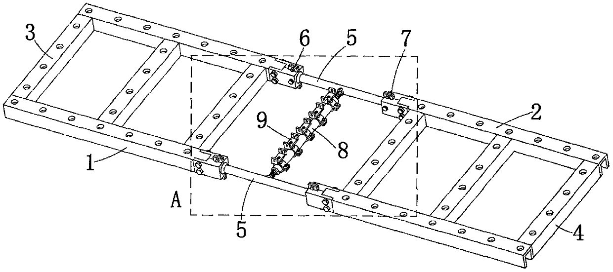
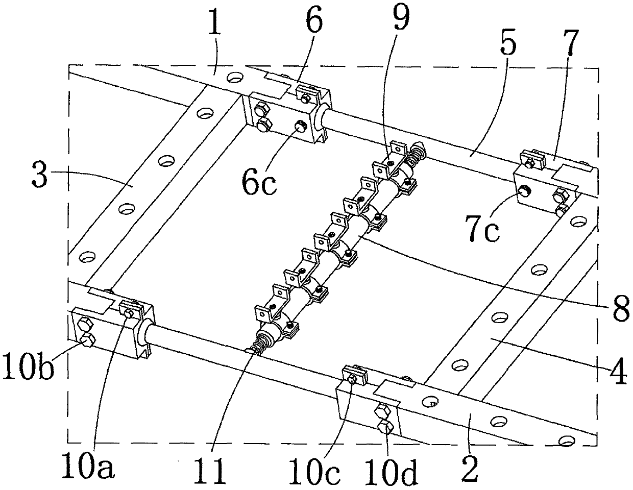
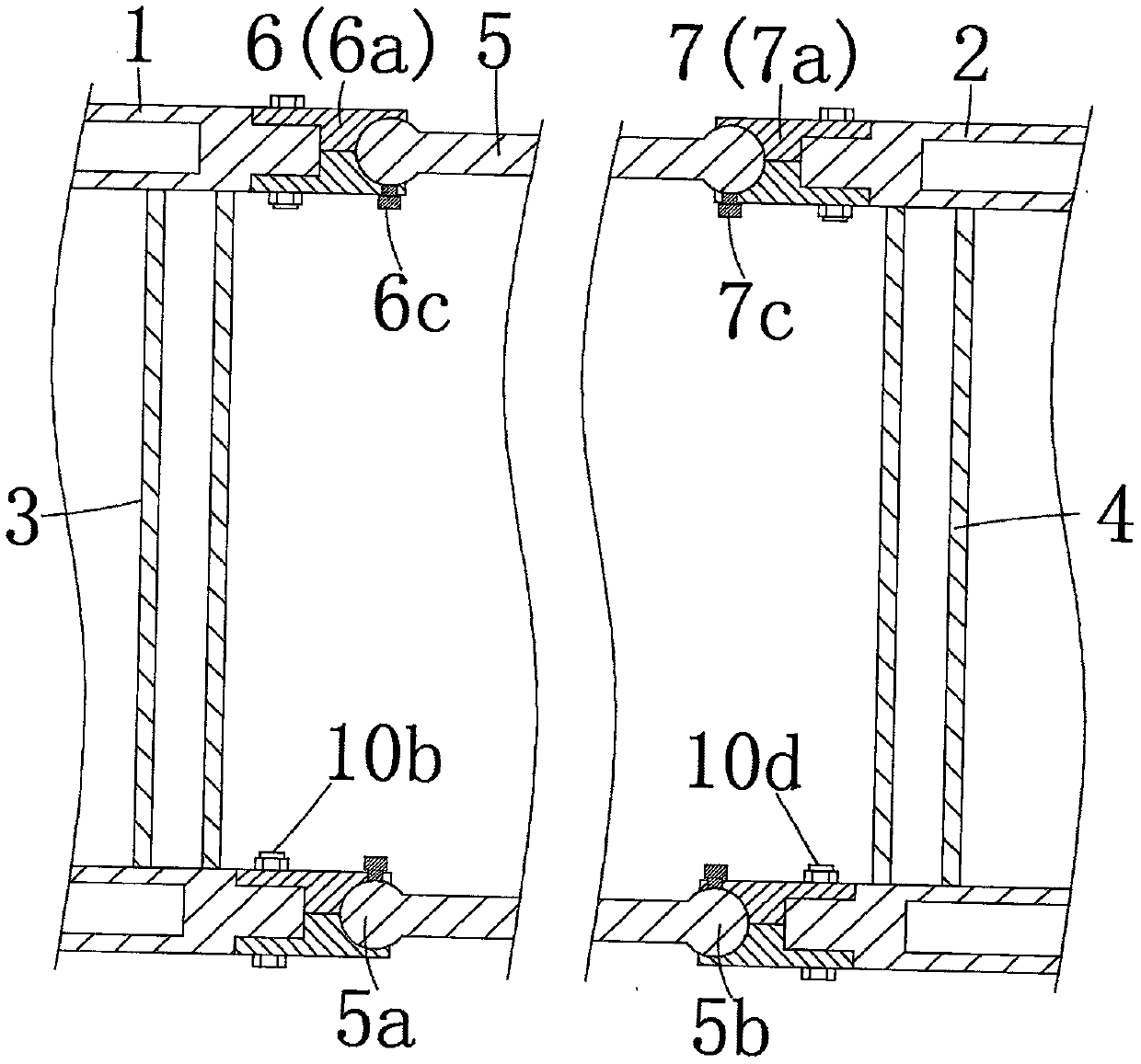
The invention discloses an aluminum alloy cabling rack and an application method. The aluminum alloy cabling rack comprises a first rack body and a second rack body and is characterized in that two sides of the first rack body are connected with two sides of the second rack body through movable connecting rods, the movable connecting rods on two sides are parallelly arranged, two ends of each movable connecting rod are respectively provided with a first ball head structure and a second ball head structure, the first rack body is provided with first ball head seats coordinated with the first ball head structures, the second rack body is provided with second ball head seats coordinated with the second ball head structures; a support rod is arranged between the movable connecting rods on twosides, and cable lap joint units are arranged on the support rod. The aluminum alloy cabling rack has the advantages that the adjusting structure of the aluminum alloy cabling rack is quite flexible,numerous use states can form between the first rack body and the second rack body, extremely high adjustability is achieved, the aluminum alloy cabling rack is especially applicable to special workingconditions, use convenience is increased greatly, on-site frame assembling and welding are not needed, and mounting convenience is increased.

Description

Technical field [0001] The invention relates to the field of wire racks for laying optical cables, in particular to an aluminum alloy wire rack and a method of use. Background technique [0002] At present, there are many types of optical cable racks, each with its own characteristics. Some cable racks are welded into a ladder-like frame. The rack is installed on the top of the room through hanging ribs, and the optical cable is fixed on the top of the rack with a tie. For the routing arrangement of optical cables, most of the existing cable racks are welded before leaving the factory. For some special structures or special needs, the installation form of the rack needs to be changed. In order to adapt to different wiring requirements, such as the need to change the laying angle of the optical cable, for the optical cable routing rack, it is necessary to place the two routing racks at the required angle, and then use other connectors to Welding is very troublesome during on-site...

Claims


Application Information

Patent Timeline
IPC IPC(8): G02B6/48
Inventor 熊怀忠
Owner HEBEI HONGYU COMM EQUIP
Why Eureka
Try Eureka