Camera shooting optical lens

An optical lens and lens technology, applied in the field of optical lenses, can solve the problems that the lens structure cannot meet the optical performance, focal power, lens distance and lens shape setting unreasonableness, etc., achieve good optical performance, correct aberrations, meet The effect of large aperture

Active Publication Date: 2019-05-31
AAC OPTICS SOLUTIONS PTE LTD
View PDF4 Cites 10 Cited by
  • Summary
  • Abstract
  • Description
  • Claims
  • Application Information

AI Technical Summary

Problems solved by technology

However, with the development of technology and the increase of diversified needs of users, as the pixel area of ​​the photosensitive device continues to shrink, and the system’s requirements for imaging quality continue to increase, the six-element lens structure gradually appears in the lens design. Common Although the six-piece lens already has good optical performance, its focal power, lens spacing and lens shape settings still have certain irrationality, resulting in a lens structure that cannot meet the needs of large aperture, large aperture, and high optical performance. Ultra-thin, wide-angle design requirements

Method used


Image

  • Camera shooting optical lens
  • Camera shooting optical lens
  • Camera shooting optical lens

Examples


no. 1 approach

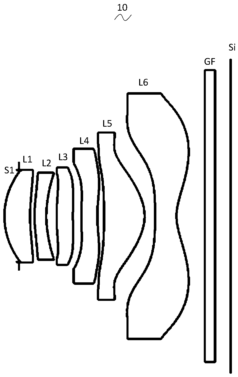
[0032] Referring to the accompanying drawings, the present invention provides an imaging optical lens 10 . figure 1 Shown is the imaging optical lens 10 of the first embodiment of the present invention, and the imaging optical lens 10 includes six lenses. Specifically, the imaging optical lens 10 includes, from the object side to the image side in sequence: an aperture S1, a first lens L1, a second lens L2, a third lens L3, a fourth lens L4, a fifth lens L5, and a sixth lens. Lens L6. In this embodiment, preferably, an optical element such as a glass plate GF is arranged between the sixth lens L6 and the image plane Si, wherein the glass plate GF can be a glass cover, or an optical filter (filter). In other possible implementation manners, the glass plate GF can also be arranged at other positions.

[0033] In this embodiment, the first lens L1 has a positive refractive power, its object side is convex outward, and its image side is concave; the second lens L2 has negative r...

no. 2 approach

[0118] Figure 5 It is a schematic structural view of the imaging optical lens 20 in the second embodiment. The second embodiment is basically the same as the first embodiment, and the symbols have the same meanings as the first embodiment. Only the differences are listed below.

[0119] Table 5 and Table 6 show the design data of the camera 20 according to the second embodiment of the present invention.

[0120] 【table 5】

[0121]

[0122] 【Table 6】

[0123]

[0124] Table 7 and Table 8 show the design data of inflection point and stagnation point of each lens in the imaging optical lens 20 of the embodiment of the present invention.

[0125] 【Table 7】

[0126]

[0127]

[0128] 【Table 8】

[0129]

Stationary number

Stationary position 1

Stationary position 2

P1R1

P1R2

1

0.835

P2R1

1

0.825

P2R2

P3R1

1

0.635

P3R2

1

0.375

P4R1

...

no. 3 approach

[0134] Figure 9 It is a schematic structural view of the imaging optical lens 30 in the third embodiment. The third embodiment is basically the same as the first embodiment, and the symbols have the same meanings as the first embodiment. Only the differences are listed below.

[0135] Table 9 and Table 10 show design data of the imaging optical lens 30 according to the third embodiment of the present invention.

[0136] 【Table 9】

[0137]

[0138] 【Table 10】

[0139]

[0140]

[0141] Table 11 and Table 12 show the design data of inflection point and stagnation point of each lens in the imaging optical lens 30 of the embodiment of the present invention.

[0142] 【Table 11】

[0143]

Number of inflection points

Inflection point position 1

Inflection point position 2

Inflection point position 3

P1R1

P1R2

1

0.625

P2R1

1

0.375

P2R2

1

0.695

P3R1

2

...


PUM


Abstract

The invention relates to the field of optical lenses, and discloses a camera shooting optical lens. The camera shooting optical lens sequentially comprises an aperture, a first lens with positive refractive power, a second lens with negative refractive power, a third lens with positive refractive power, a fourth lens with negative refractive power, a fifth lens with positive refractive power and asixth lens with negative refractive power from an object side to an image side. The focal length of the camera shooting optical lens is f, the focal length of the second lens is f2, the curvature radius of the object side face of the third lens is R5, and the curvature radius of the image side face of the third lens is R6; and the following relational expressions are met: -2.50<=(R5+R6)/(R5-R6)<=-1.00; -7.00<=f2/f<=-3.50. The camera shooting optical lens can meet the design requirements of large aperture, ultra-thinness and wide angle while having the good optical performance.

Description

technical field [0001] The invention relates to the field of optical lenses, in particular to an imaging optical lens suitable for portable terminal devices such as smart phones and digital cameras, and imaging devices such as monitors and PC lenses. Background technique [0002] In recent years, with the rise of smart phones, the demand for miniaturized photographic lenses has been increasing, and the photosensitive devices of general photographic lenses are nothing more than photocoupled devices (Charge Coupled Device, CCD) or complementary metal oxide semiconductor devices (Complementary Metal -OxideSemiconductor Sensor, CMOS Sensor), and due to the improvement of semiconductor manufacturing process technology, the pixel size of photosensitive devices has been reduced, and today's electronic products are developing with good functions and thin, light and small appearance. Therefore, it has good Miniaturized camera lenses with image quality have become the mainstream in th...

Claims


Application Information

Patent Timeline
Patent Type & Authority Applications(China)
IPC IPC(8): G02B13/00G02B13/06G02B13/18
CPCG02B13/0045G02B9/62
Inventor 陈晨曦阳孙雯
Owner AAC OPTICS SOLUTIONS PTE LTD
Why Eureka
Try Eureka