Thermal control structure of ultra-low temperature and low-energy detector

A detector and ultra-low temperature technology, applied in temperature control, instruments, measuring devices, etc., can solve the problems of no mature products, LE detector temperature fluctuation exceeds, low-temperature heat pipe has no experience in heaven, etc.

Active Publication Date: 2019-05-31
INST OF HIGH ENERGY PHYSICS CHINESE ACADEMY OF SCI
View PDF5 Cites 1 Cited by
  • Summary
  • Abstract
  • Description
  • Claims
  • Application Information

AI Technical Summary

Problems solved by technology

The multi-load integrated installation layout makes the thermal coupling between the loads with different temperature requirements very strong, but under the premise of satisfying the structural strength and rigidity, the heat insulation measures that can be realized are limited. Requirements made more difficult
[0005] 3. The change of heat flow outside the orbit is extremely complex: HXMT satellite mainly has two working modes, namely sky survey observation mode and fixed-point observation mode, and the proportion of these two modes in the entire life of the satellite is about 50%.
[0006] 4. Requirements for payload temperature stability: LE detectors are in an approximately exposed state outside the star. Under the complex external heat flow state of HXMT satellites, if effective thermal control measures are not taken, LE detectors will inevitably fail. Temperature fluctuations beyond the required temperature range
All of these have brought great difficulties to LE thermal control, which requires multi-faceted coordination to meet the requirements
[0008] 6. Low-temperature heat pipes: The main heat conduction in the current scheme relies on heat pipes, but at present, low-temperature heat pipes (below -60°C) have no experience in the sky, and there are no reliable mature products. It is necessary to solve the problems of heat conduction and reliability of low-temperature heat pipes through research

Method used


Image

  • Thermal control structure of ultra-low temperature and low-energy detector
  • Thermal control structure of ultra-low temperature and low-energy detector
  • Thermal control structure of ultra-low temperature and low-energy detector

Examples


Embodiment Construction

[0034] Exemplary embodiments of the present disclosure will be described in more detail below with reference to the accompanying drawings. Although exemplary embodiments of the present disclosure are shown in the drawings, it should be understood that the present disclosure may be embodied in various forms and should not be limited by the embodiments set forth herein. Rather, these embodiments are provided for more thorough understanding of the present disclosure and to fully convey the scope of the present disclosure to those skilled in the art.

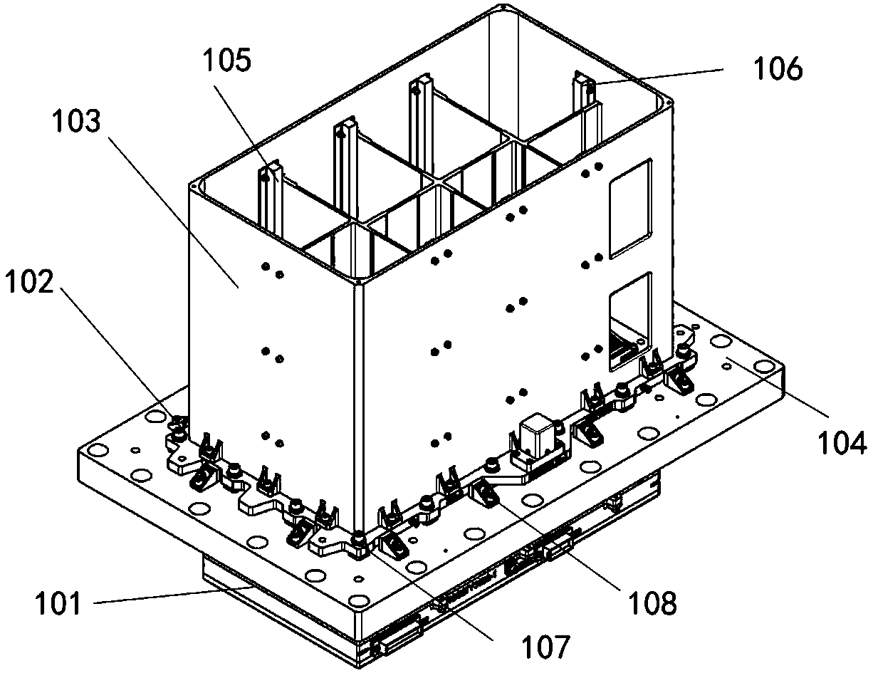
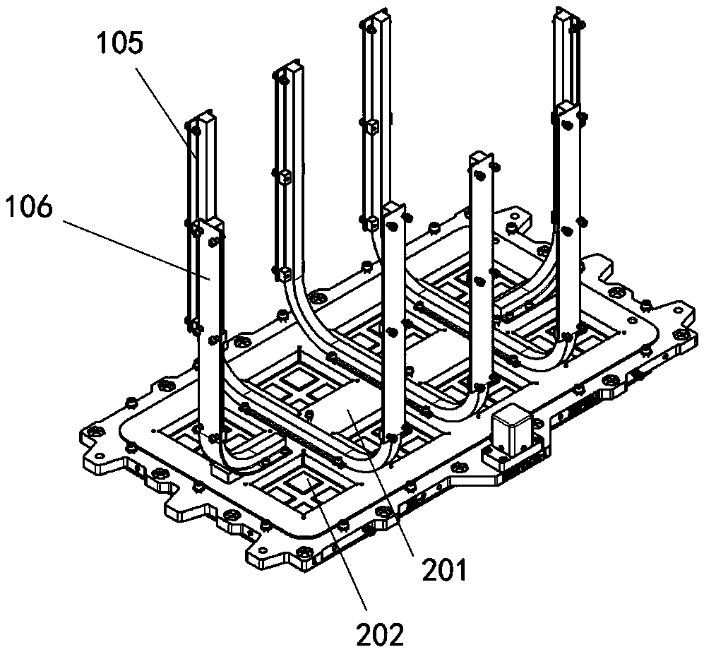
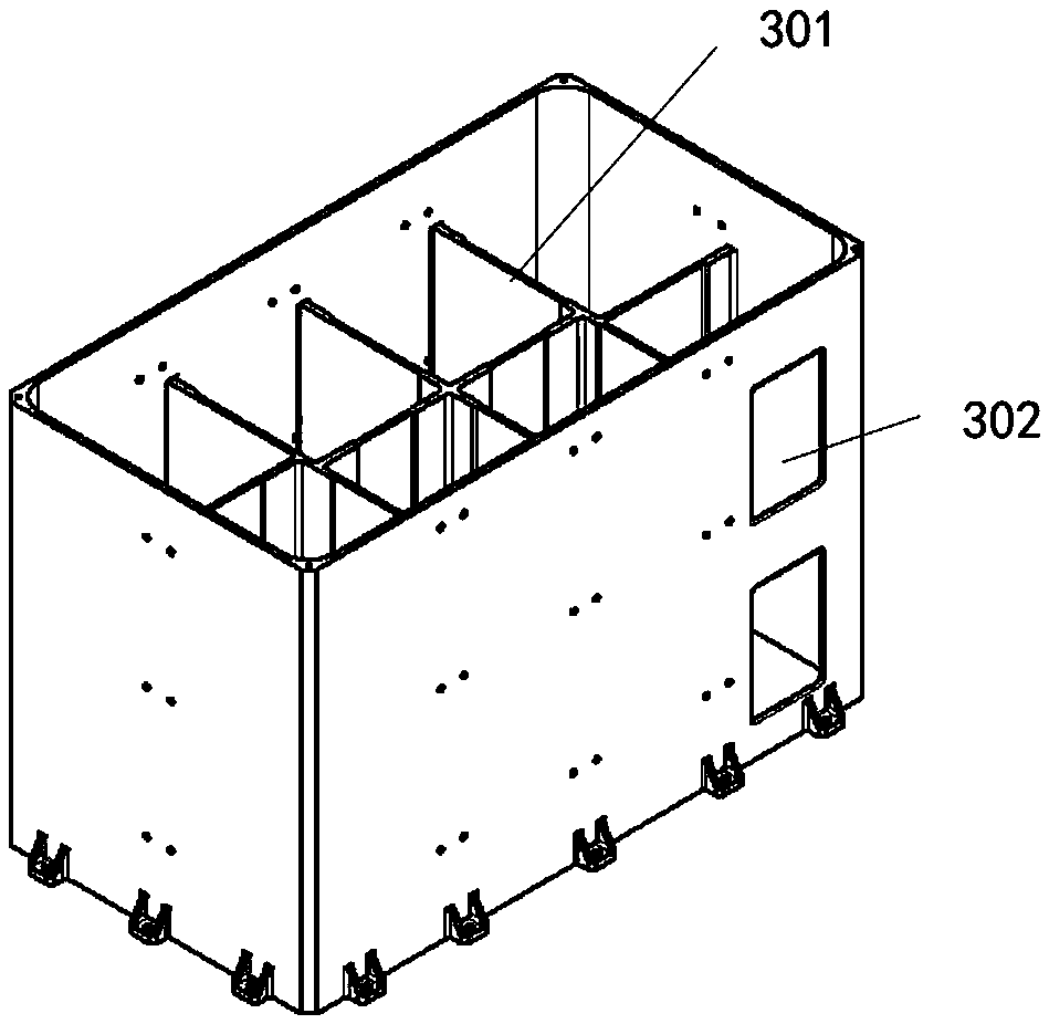
[0035] like Figure 1-5 As shown, the thermal control structure of the ultra-low temperature low-energy detector in the preferred embodiment of the present invention includes: the lower chassis 101 of the low-energy detector; Cover 103, wherein the mounting plate is provided with a slot for accommodating the collimator and the detector, and the slot is separated by a plurality of separation ribs 201; the detector 202 is fixedly ins...


PUM


Abstract

The invention provides a thermal control structure of an ultra-low temperature and low-energy detector. The structure comprises: a low energy detector lower case; a low energy detector upper case comprising a mounting plate and a shading cover fixedly connected on the mounting plate, wherein the mounting plate is provided with a slot configured to hold a collimator and a detector, and the slot isseparated by a plurality of separated edges; the detector fixedly installed in the slot of the mounting plate; the collimator installed in the slot and stacked on the detector; a simulation upper plate, wherein the mounting plate is fixed on the simulation upper plate, and the simulation upper plate can separate the low energy detector lower case from the low energy detector upper case; a U-shapedheat pipe, wherein the U-shaped bottom portion of the U-shaped heat pipe uniformly laid on the separated edges, and the two ends, extended upwards, of the U-shaped heat pipe are extended along the inner wall of the shading cover; and an L-shaped heat pipe having one end uniformly inlaid on the separated edges, wherein one end, extended upwards, of the L-shaped heat pipe is extended along the inner wall of the shading cover.

Description

technical field [0001] The invention relates to the technical field of thermal control of low-energy detectors, in particular to a thermal control structure of ultra-low-temperature low-energy detectors. Background technique [0002] LE (low-energy) thermal control is a very important key technology for low-energy X-ray telescopes. Its significance lies in that thermal control ensures the low temperature required for the normal operation of the LE detector SCD, ensures the heating of the SCD after it enters orbit, and avoids pollution problems. Guarantees a higher start-up temperature for the LE detector chassis electronics. SCD detectors have good and stable performance in the low temperature range of -80°C~-45°C. When the temperature exceeds -45°C, the dark current will increase significantly, and the energy resolution of the detector will deteriorate. The SCD package is not completely sealed, and the SCD is sensitive to pollutants. Thermal control is required to ensure t...

Claims


Application Information

Patent Timeline
Patent Type & Authority Applications(China)
IPC IPC(8): G05D23/24G01V5/00
Inventor 王娟陈勇王于仨周宇鹏赵欣张爱梅
Owner INST OF HIGH ENERGY PHYSICS CHINESE ACADEMY OF SCI
Why Eureka
Try Eureka