Installing method of low-temperature cryogenic heat pipe and assembling method of low-energy detector

A technology of installation method and assembly method, which is applied to indirect heat exchangers, lighting and heating equipment, etc., can solve the problems of complex heat flow changes outside the track, excessive temperature fluctuations of LE detectors, and no mature products.

Active Publication Date: 2019-06-11
INST OF HIGH ENERGY PHYSICS CHINESE ACADEMY OF SCI
View PDF8 Cites 0 Cited by
  • Summary
  • Abstract
  • Description
  • Claims
  • Application Information

AI Technical Summary

Problems solved by technology

The multi-load integrated installation layout makes the thermal coupling between the loads with different temperature requirements very strong, but under the premise of satisfying the structural strength and rigidity, the heat insulation measures that can be realized are limited. Requirements made more difficult
[0005] 3. The change of heat flow outside the orbit is extremely complex: HXMT satellite mainly has two working modes, namely sky survey observation mode and fixed-point observation mode, and the proportion of these two modes in the entire life of the satellite is about 50%.
[0006] 4. Requirements for payload temperature stability: LE detectors are in an approximately exposed state outside the star. Under the complex external heat flow state of HXMT satellites, if effective thermal control measures are not taken, LE detectors will inevitably fail. Temperature fluctuations beyond the required temperature range
All of these have brought great difficulties to LE thermal control, which requires multi-faceted coordination to meet the requirements
[0008] 6. Low-temperature heat pipes: The main heat conduction in the current scheme relies on heat pipes, but at present, low-temperature heat pipes (below -60°C) have no experience in the sky, and there are no reliable mature products. It is necessary to solve the problems of heat conduction and reliability of low-temperature heat pipes through research

Method used


Image

  • Installing method of low-temperature cryogenic heat pipe and assembling method of low-energy detector
  • Installing method of low-temperature cryogenic heat pipe and assembling method of low-energy detector
  • Installing method of low-temperature cryogenic heat pipe and assembling method of low-energy detector

Examples


Embodiment Construction

[0043]Exemplary embodiments of the present disclosure will be described in more detail below with reference to the accompanying drawings. Although exemplary embodiments of the present disclosure are shown in the drawings, it should be understood that the present disclosure may be embodied in various forms and should not be limited by the embodiments set forth herein. Rather, these embodiments are provided for more thorough understanding of the present disclosure and to fully convey the scope of the present disclosure to those skilled in the art.

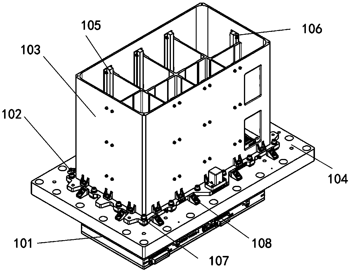
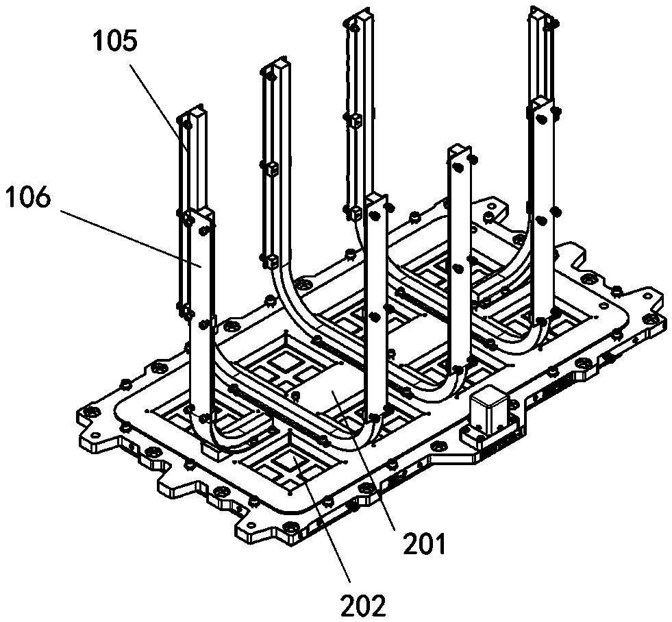
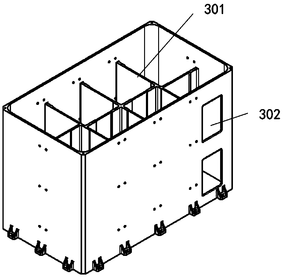
[0044] In order to facilitate the understanding of the technical solution of the present application, it is first necessary to introduce the mechanism design of the low-energy detector with heat pipe. figure 1 is a schematic diagram of the overall structure of a low-energy detector according to an embodiment of the present invention; figure 2 It is a schematic diagram of the internal structure of a heat pipe and a mounting plate ac...


PUM


Abstract

The invention provides an installing method of a low-temperature cryogenic heat pipe. The installing method of the low-temperature cryogenic heat pipe comprises the following steps that test assembling of heat pipes, light sheltering covers and installing plates is conducted before the heat pipes are filled with liquid, and parts of the heat pipes which do not meet the assembling requirements arerepaired; the vertical ends of U-shaped heat pipes and L-shaped heat pipes are installed on the inner surfaces of the light sheltering covers in a matched mode, and the outer surfaces of the light sheltering covers are pasted with second optical solar reflector (OSR) sheets; liquid filling is conducted on the heat pipes, glue removing is conducted after assembling of the heat pipes, the light sheltering cover and the installing plate is completed; a collimator is installed after all heat pipes are installed; after the light sheltering covers are installed, connecting bolts between light sheltering cover grid reinforcing ribs, the installing plate, the heat pipesand the collimator are tightened; after all parts on the upper surface are installed, and after an upper machine box is overturnedand fixed, an installing shock adsorption gasket, a detector and a detector pressing framework; after the detector pressing framework is installed, one side of the detector pressing framework is pasted with an anti-pollution heating sheet, a leading wire of the anti-pollution heating sheet penetrates through through holes of the installing plate and is thrown out of a window hole arranged on thelower part of the light sheltering cover.

Description

technical field [0001] The invention relates to the technical field of thermal control of low-energy detectors, in particular to a method for installing low-temperature cryogenic heat pipes and an assembly method for low-energy detectors. Background technique [0002] LE (low-energy) thermal control is a very important key technology for low-energy X-ray telescopes. Its significance lies in that thermal control ensures the low temperature required for the normal operation of the LE detector SCD, ensures the heating of the SCD after it enters orbit, and avoids pollution problems. Guarantees a higher start-up temperature for the LE detector chassis electronics. SCD detectors have good and stable performance in the low temperature range of -80°C~-45°C. When the temperature exceeds -45°C, the dark current will increase significantly, and the energy resolution of the detector will deteriorate. The SCD package is not completely sealed, and the SCD is sensitive to pollutants. Ther...

Claims


Application Information

Patent Timeline
Patent Type & Authority Applications(China)
IPC IPC(8): F28D15/02
Inventor 王娟陈勇王于仨周宇鹏赵欣崔苇苇
Owner INST OF HIGH ENERGY PHYSICS CHINESE ACADEMY OF SCI
Why Eureka
Try Eureka