A layout structure of cryogenic heat pipes

A technology of layout structure, cold and heat pipes, applied in space navigation equipment, space navigation aircraft, space navigation equipment, etc., can solve the problems of lack of mature products, limited heat insulation measures, difficulties and so on

Active Publication Date: 2020-06-26
INST OF HIGH ENERGY PHYSICS CHINESE ACAD OF SCI
View PDF5 Cites 0 Cited by
  • Summary
  • Abstract
  • Description
  • Claims
  • Application Information

AI Technical Summary

Problems solved by technology

The multi-load integrated installation layout makes the thermal coupling between the loads with different temperature requirements very strong, but under the premise of satisfying the structural strength and rigidity, the heat insulation measures that can be realized are limited. Requirements made more difficult
[0005] 3. The change of heat flow outside the orbit is extremely complex: HXMT satellite mainly has two working modes, namely sky survey observation mode and fixed-point observation mode, and the proportion of these two modes in the entire life of the satellite is about 50%.
[0006] 4. Requirements for payload temperature stability: LE detectors are in an approximately exposed state outside the star. Under the complex external heat flow state of HXMT satellites, if effective thermal control measures are not taken, LE detectors will inevitably fail. Temperature fluctuations beyond the required temperature range
All of these have brought great difficulties to LE thermal control, which requires multi-faceted coordination to meet the requirements
[0008] 6. Low-temperature heat pipes: The main heat conduction in the current scheme relies on heat pipes, but at present, low-temperature heat pipes (below -60°C) have no experience in the sky, and there are no reliable mature products. It is necessary to solve the problems of heat conduction and reliability of low-temperature heat pipes through research

Method used


Image

  • A layout structure of cryogenic heat pipes
  • A layout structure of cryogenic heat pipes
  • A layout structure of cryogenic heat pipes

Examples


Embodiment Construction

[0024] The specific embodiments of the present invention will be described in detail below in conjunction with the accompanying drawings, but it should be understood that the protection scope of the present invention is not limited by the specific embodiments.

[0025] Unless expressly stated otherwise, throughout the specification and claims, the term "comprise" or variations thereof such as "includes" or "includes" and the like will be understood to include the stated elements or constituents, and not Other elements or other components are not excluded.

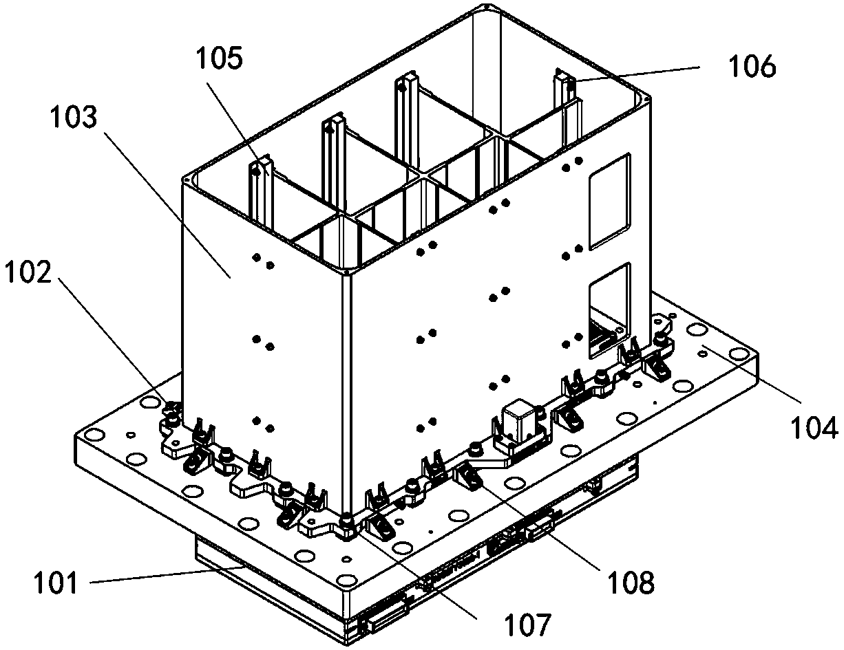
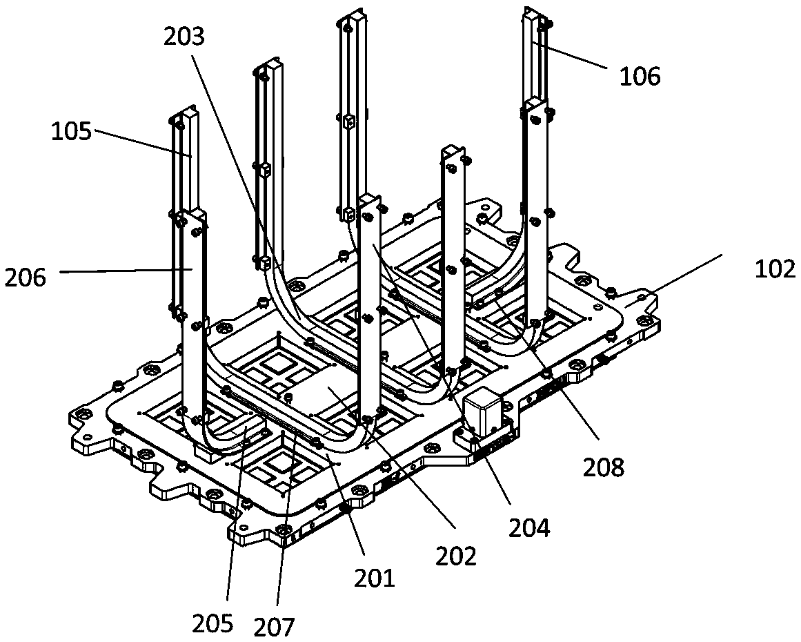
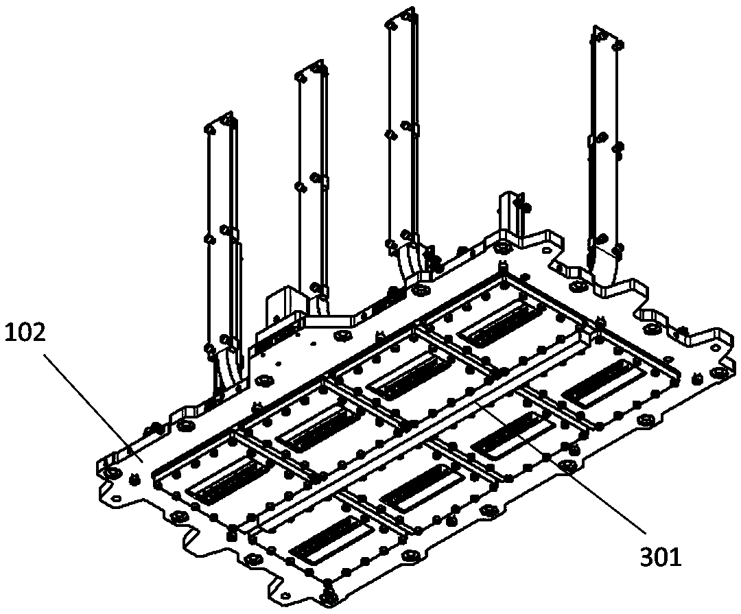
[0026] In order to facilitate the understanding of the technical solution of the present application, it is first necessary to introduce the mechanism design of the low-energy detector with heat pipe. figure 1 It is a schematic diagram of the overall structure of a low-energy detector according to an embodiment of the present invention, as shown in figure 1 As shown, the thermal control structure of the ultra-low temperatu...


PUM


Abstract

The invention discloses a layout structure of a low-temperature cryogenic heat pipe, and the layout structure comprises the following parts: a mounting plate which is provided with an open slot used for accommodating a collimator and a detector, and the open slot is separated by one or more longitudinal separation edges and one or more transverse separation edges; a U-shaped heat pipe that comprises a U-shaped heat pipe bottom and two end parts extending upwards, wherein the U-shaped heat pipe bottom of the U-shaped heat pipe is laid on the separation edges, and the two end parts extending upwards of the U-shaped heat pipe are provided with first fastening edges used for fastening the U-shaped heat pipe; an L-shaped heat pipe that comprises an L-shaped heat pipe bottom and an end part extending upwards, wherein the L-shaped heat pipe bottom is laid on the separation edges, and a second fastening edge used for fastening the L-shaped heat pipe is arranged on the end part extending upwards of the L-shaped heat pipe; a straight externally-attached heat pipe fixed on the surface of a mounting plate which is different from the U-shaped heat pipe and the L-shaped heat pipe; and a light shield fixedly connected to the mounting plate. According to the layout structure, an effective load thermal control overall design thought is formulated.

Description

technical field [0001] The invention relates to the technical field of thermal control of low-energy detectors, in particular to a layout structure of low-temperature cryogenic heat pipes. Background technique [0002] LE (low-energy) thermal control is a very important key technology for low-energy X-ray telescopes. Its significance lies in that thermal control ensures the low temperature required for the normal operation of the LE detector SCD, ensures the heating of the SCD after it enters orbit, and avoids pollution problems. Guarantees a higher start-up temperature for the LE detector chassis electronics. SCD detectors have good and stable performance in the low temperature range of -80°C~-45°C. When the temperature exceeds -45°C, the dark current will increase significantly, and the energy resolution of the detector will deteriorate. The SCD package is not completely sealed, and the SCD is sensitive to pollutants. Thermal control is required to ensure that the SCD is ...

Claims


Application Information

Patent Timeline
Patent Type & Authority Patents(China)
IPC IPC(8): B64G1/66
Inventor 王娟陈勇王于仨周宇鹏赵欣
Owner INST OF HIGH ENERGY PHYSICS CHINESE ACAD OF SCI
Why Eureka
Try Eureka