Medical imaging device and monitoring system

A monitoring system and medical imaging technology, applied in the fields of medical science, sensors, diagnostic recording/measurement, etc., can solve problems such as affecting medical imaging equipment, increasing installation costs, inability to synchronize inspection process operation and monitoring in real time, etc., to achieve the same screen Displayed effect

Inactive Publication Date: 2019-06-04
裴嘉豪
View PDF0 Cites 2 Cited by
  • Summary
  • Abstract
  • Description
  • Claims
  • Application Information

AI Technical Summary

Problems solved by technology

[0003] However, currently all such monitoring equipment are third-party products other than medical imaging equipment, and are installed later, which is not good for the power wiring and aesthetics of the entire medical imaging equipment, and increases additional installation costs
In addition, these monitoring devices may interfere with the performance of some parameters of medical imaging equipment, thereby affecting the best results of medical imaging equipment
[0004] Furthermore, during use, since the display system of such monitoring equipment is usually independent of the medical imaging equipment, the operator not only needs to pay attention to the status of the workstation of the medical imaging equipment, but also needs to pay attention to the status of the examinee on the display of the monitoring equipment. , the operator cannot operate the medical imaging equipment and monitor in real time on the same screen at the same time, and the operation and monitoring of the inspection process cannot be synchronized in real time. There is a certain risk of misoperation or failure to detect abnormal dynamics of the subject

Method used


Image

  • Medical imaging device and monitoring system
  • Medical imaging device and monitoring system
  • Medical imaging device and monitoring system

Examples


Embodiment Construction

[0033] Reference will now be made in detail to the exemplary embodiments, examples of which are illustrated in the accompanying drawings. When the following description refers to the accompanying drawings, the same numerals in different drawings refer to the same or similar elements unless otherwise indicated. The implementations described in the following exemplary embodiments do not represent all implementations consistent with this application. Rather, they are merely examples of apparatuses and methods consistent with aspects of the present application as recited in the appended claims.

[0034] The terminology used in this application is for the purpose of describing particular embodiments only, and is not intended to limit the application. As used in this application and the appended claims, the singular forms "a", "the", and "the" are intended to include the plural forms as well, unless the context clearly dictates otherwise. It should also be understood that the term...


PUM


Abstract

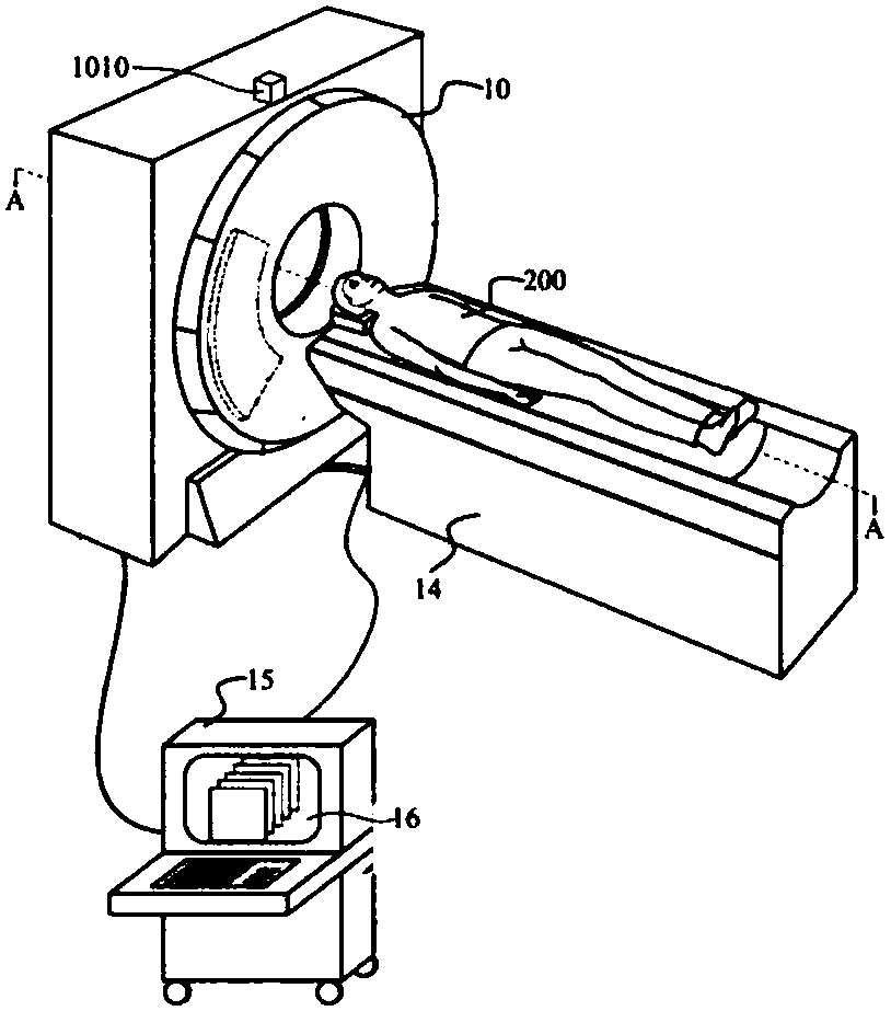
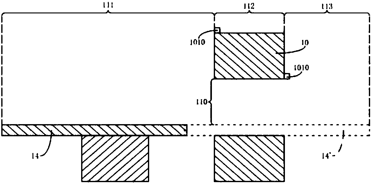
The present invention provides a medical imaging device and a monitoring system for the medical imaging device. The monitoring system is integrated into the medical imaging device, and includes: a monitoring terminal, which is integrally disposed on a scanning frame of the medical imaging device, wherein a monitoring range of the monitoring terminal covers the full motion range of a scanning bed of the imaging device; and a display terminal connected to the monitoring terminal and arranged in a workstation of the medical imaging device, wherein the image information collected by the monitoringterminal is displayed on a display of the workstation together with the scanned image of the medical imaging device through the display terminal. The monitoring system of the present application integrates the monitoring terminal and the display terminal of the monitoring system with the medical imaging device, and the image information displayed on the display terminal and the scanned image of the medical imaging device are displayed together on the display of the workstation of the medical imaging device used by an operator, the operation, guidance of a subject, and monitoring are subjectedto real-time synchronized display on the same screen, which can achieve real-time monitoring, scanning and monitoring on the same screen display by the medical imaging device.

Description

technical field [0001] The present application relates to the technical field of medical equipment, in particular to medical imaging equipment and a monitoring system for the equipment. Background technique [0002] At present, after large-scale medical equipment such as CT, MR, PET / CT, PET / MR, TOMO, etc. are installed in hospitals and other medical institutions, in order to monitor the real-time status of the examinee during the use process, or To instruct them to accept the inspection in the correct posture, several monitoring probes are usually installed in the equipment room, and a monitoring monitor is placed on the equipment console to facilitate the coordination of monitoring and control. [0003] However, currently all such monitoring equipment are third-party products other than medical imaging equipment, and are installed later, which is not good for the power wiring and aesthetics of the entire medical imaging equipment, and increases additional installation costs...

Claims


Application Information

Patent Timeline
Patent Type & Authority Applications(China)
IPC IPC(8): A61B6/03A61B5/055
Inventor 裴嘉豪
Owner 裴嘉豪
Why Eureka
Try Eureka