Floor tile laying and pasting device

A technology of floor tiles and suction cups, which is applied in the direction of construction and building construction, can solve the problems of time-consuming and labor-intensive laying of floor tiles, and achieve the effects of reducing work intensity, increasing contact area, and simple structure

Inactive Publication Date: 2019-06-04
颜耀权
View PDF6 Cites 0 Cited by
  • Summary
  • Abstract
  • Description
  • Claims
  • Application Information

AI Technical Summary

Problems solved by technology

[0004] In order to solve the above-mentioned problems in the prior art, the present invention provides a floor tile laying device to solve the time-consuming and laborious technical problem of floor tile laying in the prior art

Method used


Image

  • Floor tile laying and pasting device
  • Floor tile laying and pasting device
  • Floor tile laying and pasting device

Examples


Embodiment 1

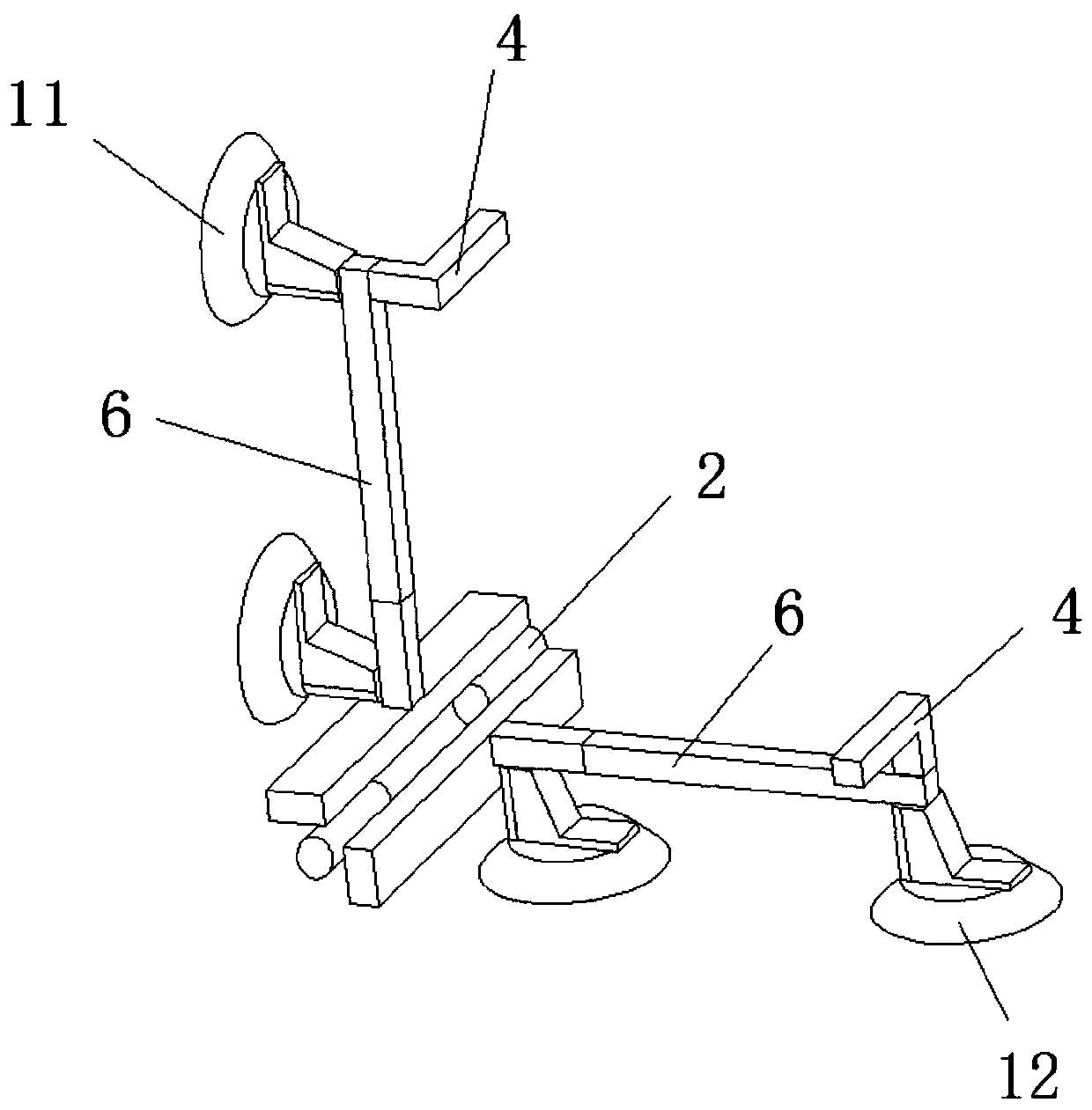
[0031] A floor tile laying device, such as figure 1 As shown, it includes a first suction cup group 11, a second suction cup group 12 and a hinge assembly, the first suction cup group 11 and the second suction cup group 12 are hinged by the hinge assembly, and when the hinge assembly is in an unfolded state, the first suction cup group 11 The orientation of the adsorption surfaces of the second suction cup set 12 is the same, and when the hinge assembly is in the closed state, the orientations of the adsorption surfaces of the first suction cup set 11 and the second suction cup set 12 are opposite.

[0032] Through a floor tile laying device with the above structure, when in use, the worker can use the first suction cup group 11 and the second suction cup group 12 to respectively absorb a floor tile, and then move the two floor tiles to the position where they need to be pasted. At this time, The worker just can realize the trial placement of floor tiles by pulling the first s...

Embodiment 2

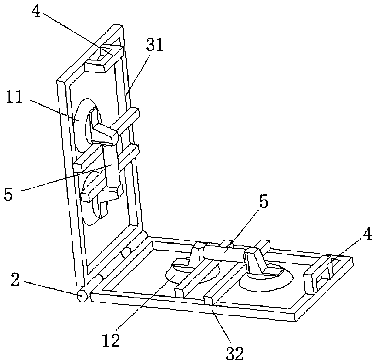
[0040] As another specific structure of the present invention, such as figure 2 As shown, the floor tile laying device includes a first suction cup group 11, a second suction cup group 12 and a hinge assembly, the first suction cup group 11 and the second suction cup group 12 are hinged by the hinge assembly, and when the hinge assembly is in an unfolded state, the second suction cup assembly The suction surfaces of the first suction cup set 11 and the second suction cup set 12 have the same orientation, and when the hinge assembly is in the closed state, the suction surfaces of the first suction cup set 11 and the second suction cup set 12 have opposite orientations.

[0041] Optimally, the hinge assembly includes a first frame 31, a second frame 32 and a hinge 2; wherein,

[0042] Both the first frame 31 and the second frame 32 are quadrangular frames, one of the action ends of the hinge 2 is connected to one side of the first frame 31, and the other action end of the hinge 2...


PUM


Abstract

The invention belongs to the technical field of floor tile laying and pasting equipment, and particularly relates to a floor tile laying and pasting device. The floor tile laying and pasting device comprises a first suction disc group, a second suction disc group and a hinging assembly, wherein the first suction disc group and the second suction disc group are hinged through the hinging assembly;when the hinging assembly is in an unfolded state, the facing directions of the adsorption surfaces of the first suction disc group and the second suction disc group are identical; and when the hinging assembly is in a closed state, the facing directions of the adsorption surfaces of the first suction disc group and the second suction disc group are opposite. In the use process, a worker can use the first suction disc group and the second suction disc group for respectively adsorbing a floor tile; then, the first suction disc group or the second suction disc group is turned for realizing the floor tile turning; the floor tile turning process by the worker is simpler and more convenient, so that the work intensity of the worker is reduced; the floor tile laying and pasting work efficiency is effectively improved; and the floor tile turning is realized by turning the first suction disc group or the second suction disc group, so that the occurrence of the condition that the hand of the worker is injured by the floor tile can be avoided.

Description

technical field [0001] The invention belongs to the technical field of floor tile laying equipment, and in particular relates to a floor tile laying device. Background technique [0002] At present, in the construction and decoration industry, most of the laying of floor tiles is done manually; [0003] In the process of paving floor tiles, the workers have to make several trial placements on the installation position in the process of paving each floor tile, then turn the floor tiles over, and apply the paste material on the back of the floor tiles, and then place the floor tiles Laying and pasting at the corresponding position; due to the large size of the floor tiles and the weight of several kilograms, the workers become more time-consuming and laborious in the process of laying the floor tiles, and the high labor intensity is easy to cause fatigue of the workers, thereby reducing the floor tiles. At the same time, in the process of turning the floor tiles, the floor ti...

Claims


Application Information

Patent Timeline
Patent Type & Authority Applications(China)
IPC IPC(8): E04F21/22
Inventor 颜耀权
Owner 颜耀权
Why Eureka
Try Eureka