
Dust removing device for open pit mine

A technology for dust removal devices and open-pit mines, applied in safety devices, dust prevention, mining equipment, etc., can solve problems such as insecurity, motors are easy to enter dust or water, etc., to increase the layout space, increase the dust removal coverage area, and increase the spray volume Effect

Active Publication Date: 2019-06-04
江西核工业建设有限公司
View PDF6 Cites 0 Cited by
  • Summary
  • Abstract
  • Description
  • Claims
  • Application Information

AI Technical Summary

Problems solved by technology

The dust suppression device adopted by this mechanism sprays through the high-pressure nozzle. Under the action of the fan, the coverage area of ​​the spray is increased. During long-term use, the fan works in a dusty and humid environment for a long time, and dust can easily enter the motor. or water, there are unsafe factors

Method used


Image

  • Dust removing device for open pit mine
  • Dust removing device for open pit mine
  • Dust removing device for open pit mine

Examples


Embodiment 1

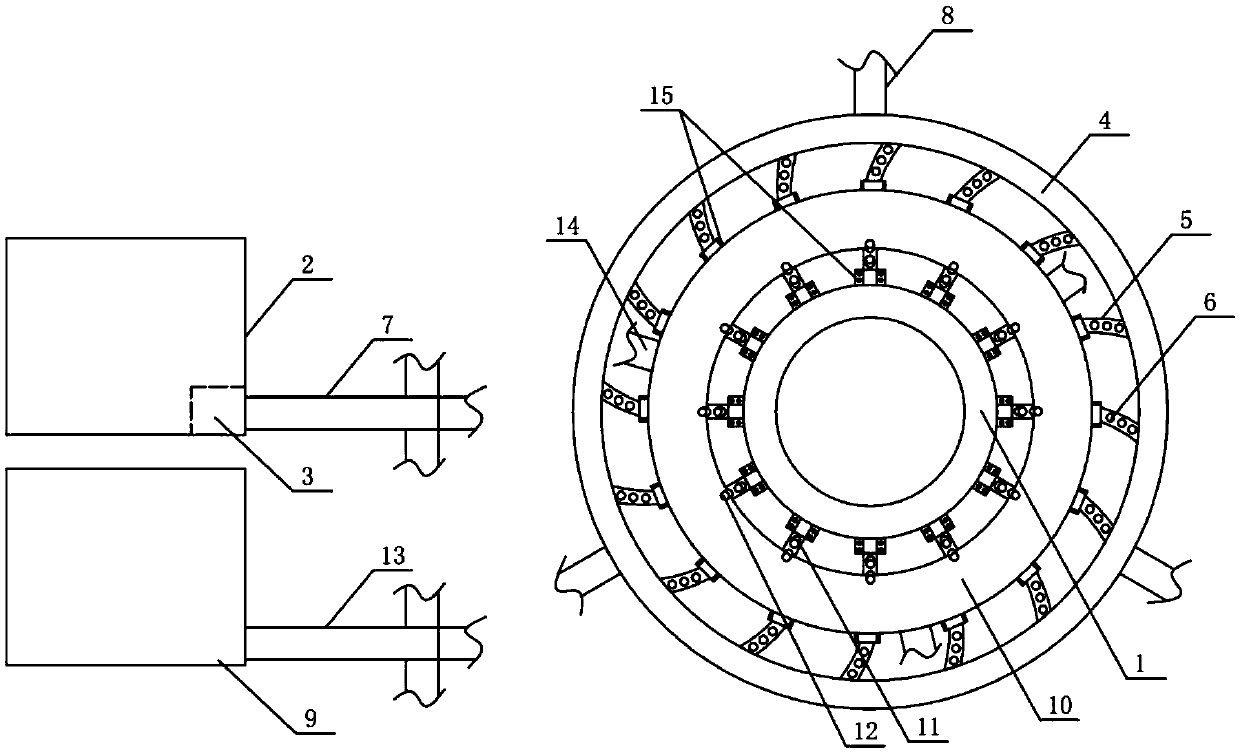
[0027] Such as figure 1 , the present invention is a planar structure, which sequentially includes a spray device, an air injection device and a support seat 1 from the outside to the inside, and the support seat 1 is an annular structure;

[0028] The spraying device includes a water tank 2, a water pump 3, a water supply pipe and a high-pressure water distribution main pipe 4. The water pump 3 is located in the water tank 2. The water pump 3 communicates with the high-pressure water distribution main pipe 4 through the water supply pipe. The high-pressure water distribution main pipe 4 is a ring structure. Sixteen high-pressure water distribution branch pipes 5 are connected to the inner side of the distribution main pipe 4. The high-pressure water distribution branch pipes 5 are located between the high-pressure water distribution main pipe 4 and the air injection device. Three spray heads 6 are evenly arranged on each high-pressure water distribution branch pipe 5. The wat...

Embodiment 2

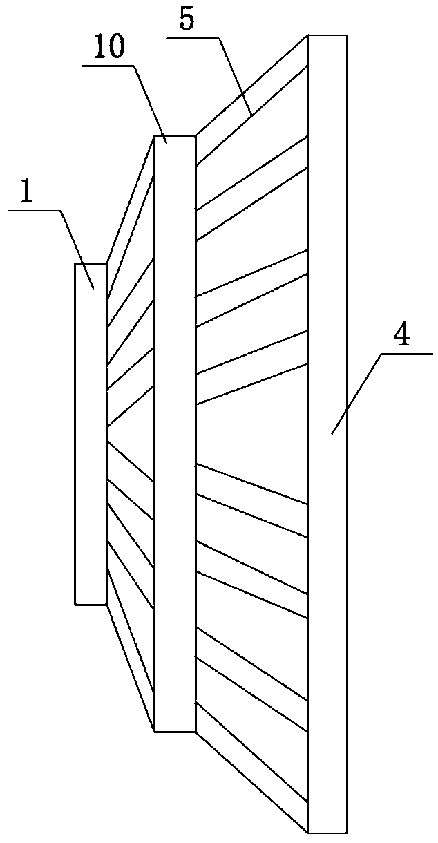
[0033] The structure of this embodiment is basically the same as that of Embodiment 1, the difference is: as figure 2 As shown, the dust removal device disclosed by the present invention is a frustum-shaped structure, the high-pressure water distribution branch pipe 5 is a straight pipe, the area of ​​the circle where the support seat 1 is located, the area of ​​the circle where the high-pressure air distribution main pipe 10 is located, and the area of ​​the circle where the high-pressure water distribution main pipe 4 is located increase in turn.

[0034] In this embodiment, the dedusting device is designed as a truncated cone structure, which can increase the overlapping area of ​​the spray and air injection, and further enhance the spray area of ​​the present invention.


PUM


Abstract

The invention discloses a dust removing device for open pit mine. The dust removing device sequentially comprises a mist spraying device, an air spraying device and a supporting seat from outside to inside; the mist spraying device comprises a water tank, a water pump, a water supplying pipe and a high-pressure water distribution main pipe, the high-pressure water distribution main pipe is of an annular structure, a plurality of high-pressure water distribution branch pipes are arranged on the inner side of the high-pressure water distribution main pipe in a communicating mode, and a pluralityof mist spraying heads are evenly arranged on the high-pressure water distribution branch pipes; the air spraying device comprises an air compressor, an air supplying pipe and a high-pressure air distribution main pipe, the high-pressure air distribution main pipe is of an annular structure, a plurality of high-pressure air distribution branch pipes are arranged on the inner side of the high-pressure air distribution main pipe in a communicating mode, and a plurality of air spraying heads are evenly arranged on the high-pressure air distribution branch pipes; and the inner ends of the high-pressure water distribution branch pipes and the inner ends of the high-pressure air distribution branch pipes are each of a closed structure. According to the dust removing device, a dust suppression mechanism arranged in the field for operation does not involve electrical components, and the safety in the using process is effectively ensured.

Description

technical field [0001] The invention belongs to the technical field of mining equipment, and in particular relates to a dust removal device for open-pit mines. Background technique [0002] In the mining process of open-pit mines, due to the use of various large-scale mobile machinery, dust and toxic gases have increased greatly. Through the dust detection on site, loading equipment, transportation equipment, and mining equipment are the main dust-producing equipment. [0003] Practice has proved that taking appropriate dust control measures according to the operating characteristics of each link can achieve good dust suppression effects. Usually, mining equipment will be equipped with corresponding dust suppression equipment to achieve instant dust suppression as mining progresses. However, for Due to the fluidity of the process, the dust generated by the installation and transportation equipment needs to be sprayed with water on a large area to suppress the dust on the job...

Claims


Application Information

Patent Timeline
IPC IPC(8): E21F5/04
Inventor 王利陈凯文李亚娟
Owner 江西核工业建设有限公司
Learn More