Pneumatic tire

A technology of pneumatic tires and tires, which is applied to heavy tires, tire parts, tire treads/tread patterns, etc., which can solve the problems of reduced ride comfort and uneven wear, and achieve the effect of low noise

Active Publication Date: 2019-06-04
THE YOKOHAMA RUBBER CO LTD
View PDF14 Cites 0 Cited by
  • Summary
  • Abstract
  • Description
  • Claims
  • Application Information

AI Technical Summary

Problems solved by technology

[0002] In a pneumatic tire, a plurality of grooves are formed on the tread surface for the purpose of draining water between the tread surface and the road surface when driving on a slippery road, but on the other hand, the grooves on the tread surface also become Causes of uneven wear and reduced ride comfort

Method used


Image

  • Pneumatic tire
  • Pneumatic tire
  • Pneumatic tire

Examples


Embodiment Construction

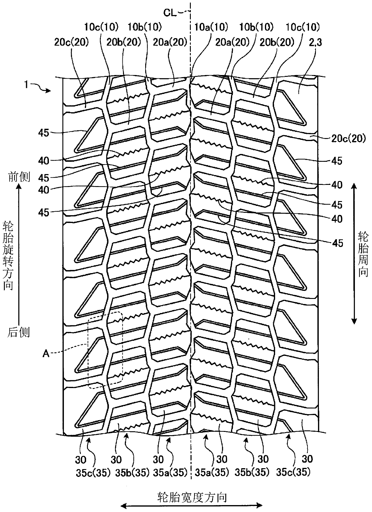
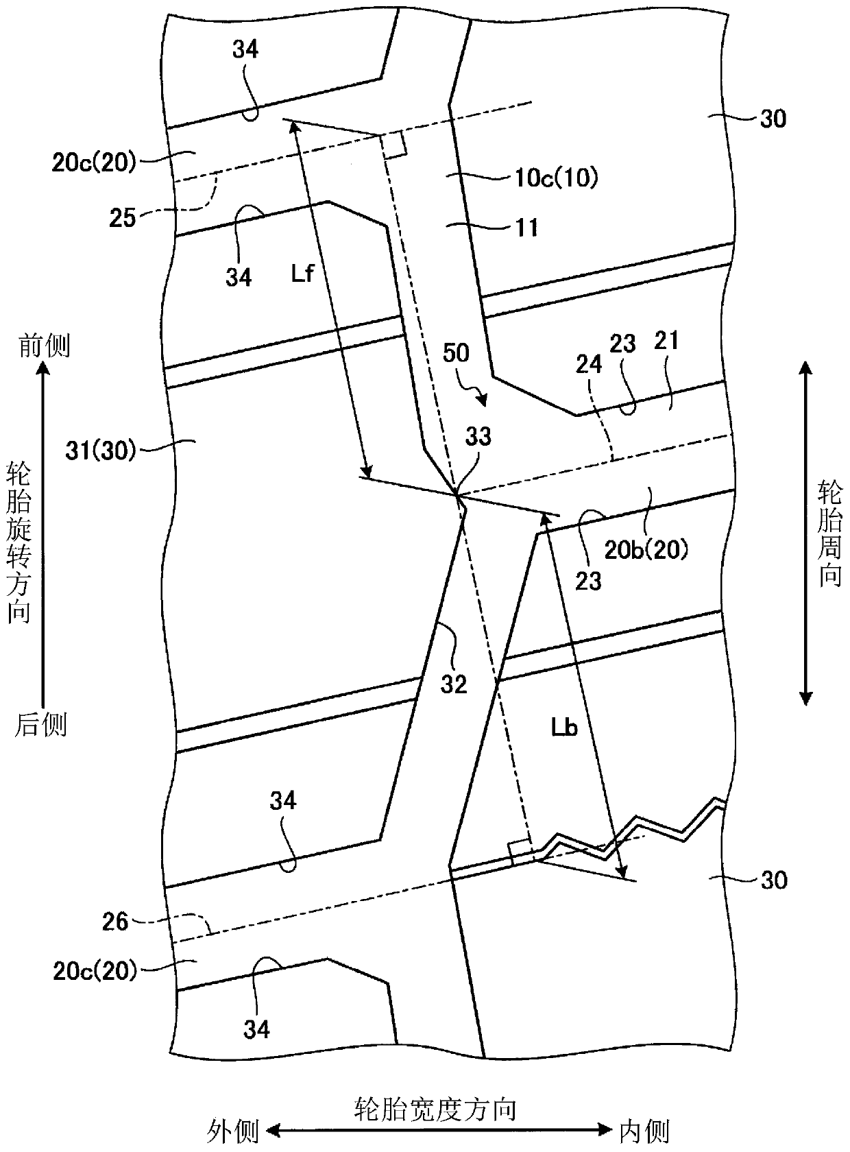
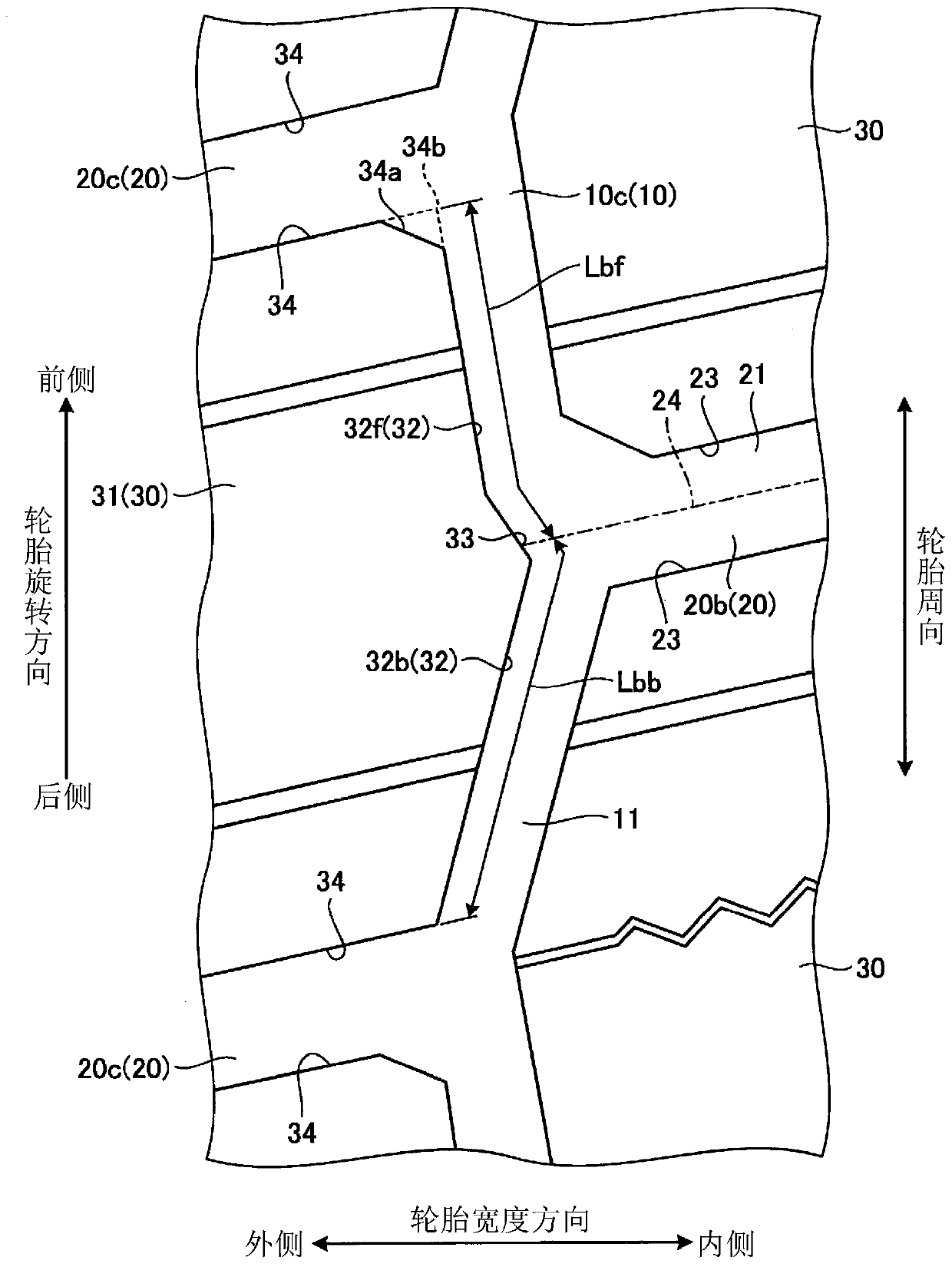
[0027] Hereinafter, embodiments of the pneumatic tire of the present invention will be described in detail based on the drawings. It should be noted that the present invention is not limited by this embodiment. In addition, the constituent elements of the following embodiments include elements that can be replaced and easily conceived by those skilled in the art, or elements that are substantially the same.

[0028] In the following description, the tire width direction means the direction parallel to the rotation axis of the pneumatic tire, the tire width direction inside means the direction toward the tire equator line in the tire width direction, and the tire width direction outside means the direction toward the tire width direction. Opposite direction of the direction of the equator line. In addition, the tire radial direction means a direction perpendicular to the tire rotational axis, and the tire circumferential direction means a direction that rotates around the tire...


PUM


Abstract

In a pneumatic tire (1) of which the rotation direction is specified in order to achieve noise reduction while maintaining wet performance, when: a circumferential main groove (10) that forms an intersection section (50) at which a lug groove (20) is connected to the circumferential main groove (10) from the inner side in the tire width direction is defined as an intersection circumferential maingroove (11); the lug groove (20) that forms the intersection section (50) is defined as an intersection lug groove (21); a block (30) demarcated at the inner side thereof in the tire width direction by the intersection circumferential main groove (11) is defined as an intersection block (31); and an intersection point of an intersection lug groove center line (24) which is the center line of the intersection lug groove (21) and an edge section (32) on the side of the intersection block (31) demarcated by the intersection circumferential main groove (11) is defined as a center line intersectionpoint (33), the relationship between the distance Lf from the center line intersection point (33) to the center line of the lug groove (20) that demarcates the front side, in the tire rotation direction, of the intersection block (31), and the distance Lb from the center line intersection point (33) to the center line of the lug groove (20) that demarcates the rear side, in the tire rotation direction, of the intersection block (31), falls within the range of 1.0 <= (Lb / Lf) <= 1.2.

Description

technical field [0001] The present invention relates to a pneumatic tire. Background technique [0002] In a pneumatic tire, a plurality of grooves are formed on the tread surface for the purpose of draining water between the tread surface and the road surface when running on a slippery road, but on the other hand, the grooves on the tread surface also become Causes of uneven wear and reduced ride comfort. Therefore, in conventional pneumatic tires, the reduction of uneven wear and ride comfort are ensured by designing the shape and arrangement of the grooves. [0003] For example, the pneumatic tire described in Patent Document 1 improves drainage performance and wear resistance performance in a balanced manner by specifying the groove width of a so-called block pattern, the land ratio between predetermined regions, and the groove angle. In addition, the pneumatic tire described in Patent Document 2 maintains ride comfort and drainage performance and improves run-flat per...

Claims


Application Information

Patent Timeline
Patent Type & Authority Applications(China)
IPC IPC(8): B60C11/03B60C11/13
CPCB60C11/0302B60C11/0306B60C2011/0344B60C2011/0346B60C2011/0353B60C2011/0372B60C2200/06B60C11/03B60C11/0304B60C11/0309B60C11/11B60C11/13
Inventor 田村将司
Owner THE YOKOHAMA RUBBER CO LTD
Why Eureka
Try Eureka