Cutter disc structure of digital controlled lathe

A technology of CNC lathes and cutterheads, applied in the direction of tool holders, etc., can solve problems such as poor product concentricity and smoothness, inability to adjust the tool bar, and inability to achieve processing, so as to reduce manpower input, shorten processing time, and improve processing efficiency. high effect

Pending Publication Date: 2019-06-07
邹洪波
View PDF0 Cites 5 Cited by
  • Summary
  • Abstract
  • Description
  • Claims
  • Application Information

AI Technical Summary

Problems solved by technology

However, the existing cutter head structure is too single, and each feed can only be processed by a single knife, and the processing efficiency is low; and each tool can only carry out one processing process, and the processing position is relatively single, and the workpiece needs to be processed many times. The concentricity and smoothness of the product are not good; in addition, the ordinary cutterhead structure, the cutter bar cannot be adjusted, and the processing purpose cannot be achieved for more complex workpieces, which has certain limitations on the scope of application of the processed workpieces.

Method used


Image

  • Cutter disc structure of digital controlled lathe
  • Cutter disc structure of digital controlled lathe
  • Cutter disc structure of digital controlled lathe

Examples


Embodiment Construction

[0019] It should be understood that the specific embodiments described here are only used to explain the present invention, not to limit the present invention.

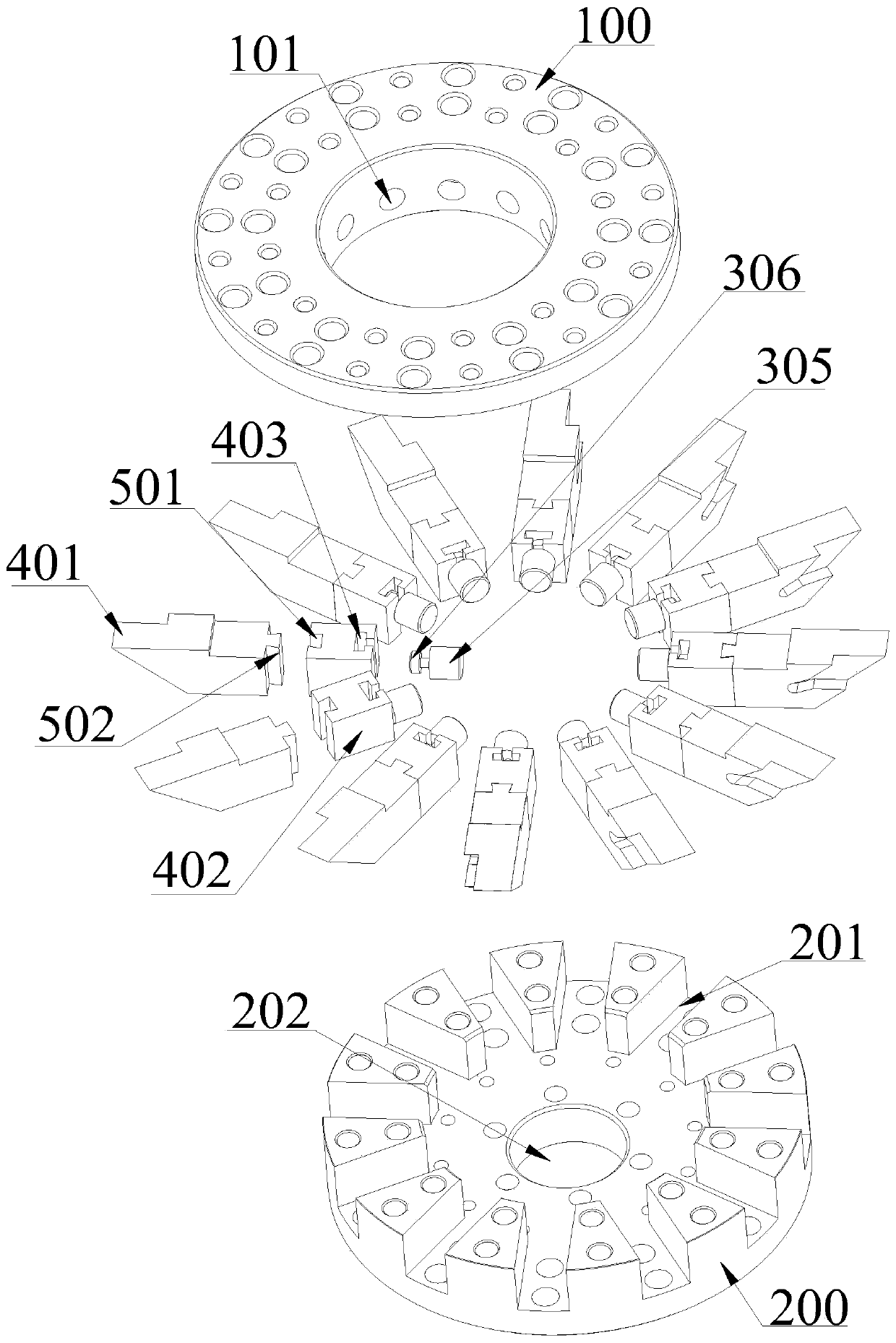
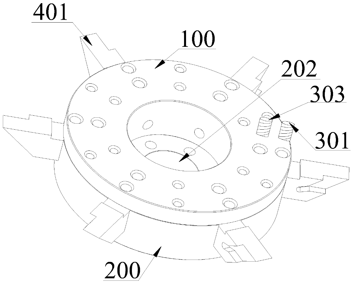
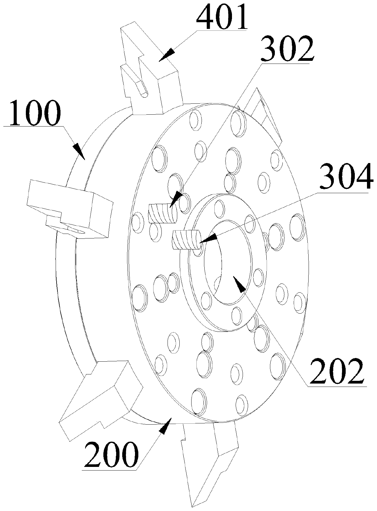
[0020] refer to Figure 1 to Figure 4 , an embodiment of the cutterhead structure of a CNC lathe according to the present invention is proposed. The cutterhead structure is set on the electric spindle 600 of the CNC lathe and processes the workpiece 800 on the spindle 700 of the lathe. The cutterhead structure includes a cutterhead body and several cutter bar structures clamped in the cutterhead body. The cutterhead body includes a fixed disk 100 and a cutterhead back seat 200, wherein the fixed disk 100 and the cutter head back seat 200 are connected by screws. Locking and fixing, compact structure and firm connection.

[0021] A plurality of installation slots 201 are provided on the cutterhead rear seat 200 , and the cutter bar structure is embedded in the installation slots 201 . The cutter bar structure is set ...


PUM


Abstract

The invention discloses a cutter disc structure of a digital controlled lathe. The cutter disc structure of the digital controlled lathe comprises a cutter disc body and multiple cutter rod structures, wherein each cutter rod structure is arranged to be of a separated structure comprises a front end part and a back end part; the front end parts and the back end parts are spliced through dovetail groove structures; upper outer screws and lower outer screws rotatably and tightly pressed on the front end parts are arranged on the cutter disc body; upper inner screws and lower inner screws rotatably and tightly pressed on the back end parts are arranged on the cutter disc body; and adjusting screws capable of adjusting the positions of the cutter rod structures after being screwed are arrangedon the inner side wall of the cutter disc body. According to the cutter disc structure provided by the invention, multiple lathe tools are gathered on the cutter disc body, the cutter rod structuresadopts the separated structures, the positions of the cutter rod structures are flexibly adjusted through the upper outer screws, the lower outer screws, the upper inner screws and the lower inner screws, namely, the feeding direction, the feeding angle and the feeding position of the lathe tools are adjusted, and the cutter disc structure can accomplish multiple processing procedures after processing through a common cutter at one time, so that the processing efficiency is high, the manpower is saved, and the concentricity and the smoothness of the processed product are ensured.

Description

technical field [0001] The invention relates to the technical field of mechanical equipment, in particular to a cutterhead structure of a numerically controlled lathe. Background technique [0002] The cutter head is the installation part of the turning tool bar on the CNC lathe. The tool bar is fixed on the cutter head body, and then the lathe spindle drives the workpiece to rotate and the turning tool cuts the workpiece, so as to realize the purpose of processing the workpiece. However, the existing cutter head structure is too single, and each feed can only be processed by a single knife, and the processing efficiency is low; and each tool can only carry out one processing process, and the processing position is relatively single, and the workpiece needs to be processed many times. The concentricity and smoothness of the product are not good when the process is processed; in addition, the ordinary cutterhead structure, the cutter bar cannot be adjusted, and the processing...

Claims


Application Information

Patent Timeline
Patent Type & Authority Applications(China)
IPC IPC(8): B23B29/24
Inventor 邹洪波
Owner 邹洪波
Why Eureka
Try Eureka