Movement mechanism for synchronization action of cutters and cutting knife

A technology of synchronous action and motion mechanism, applied in metal processing and other directions, can solve the problems of easily damaged plates, labor, material collapse, etc., and achieve the effects of easy portability, reduced volume, and reduced cutting area.

Pending Publication Date: 2019-06-07
QINGDAO CHENBA IND & TRADE CO LTD
View PDF11 Cites 1 Cited by
  • Summary
  • Abstract
  • Description
  • Claims
  • Application Information

AI Technical Summary

Problems solved by technology

[0006] The invention provides a kinematic mechanism and a cutting knife for the synchronous action of the knives, which are used to solve the problems that the existing cutting knives are laborious in use, easy to damage the plate, and prone to material collapse and flying.

Method used


Image

  • Movement mechanism for synchronization action of cutters and cutting knife
  • Movement mechanism for synchronization action of cutters and cutting knife
  • Movement mechanism for synchronization action of cutters and cutting knife

Examples


Embodiment Construction

[0031] In order to make the purpose, technical solutions and advantages of the embodiments of the present invention clearer, the technical solutions in the embodiments of the present invention will be clearly and completely described below in conjunction with the drawings in the embodiments of the present invention. Obviously, the described embodiments It is a part of embodiments of the present invention, but not all embodiments. Based on the embodiments of the present invention, all other embodiments obtained by persons of ordinary skill in the art without creative efforts fall within the protection scope of the present invention.

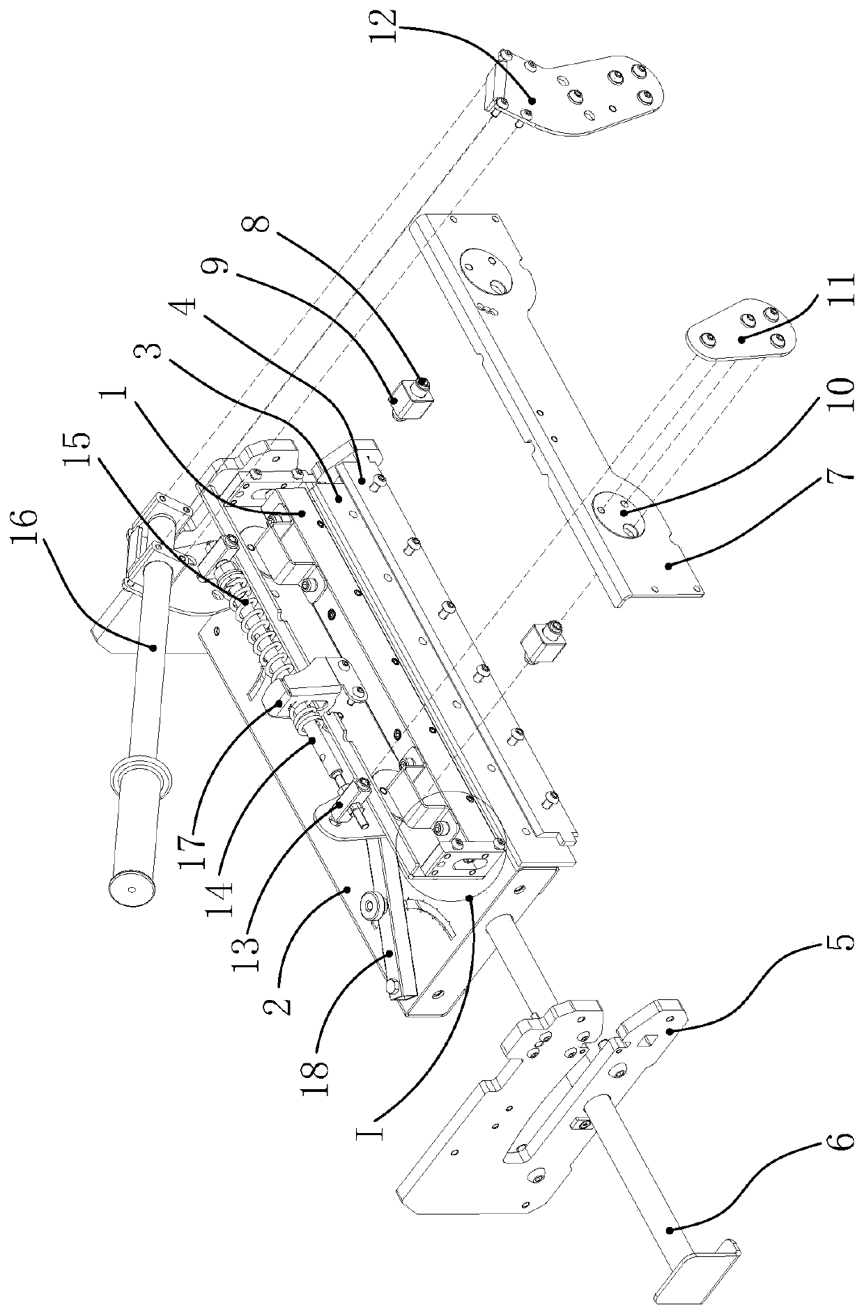
[0032] For the convenience of understanding and describing this embodiment, with figure 1 The left and right sides shown are vertical, and the corresponding expressions are front end and rear end, figure 1 The top and bottom shown are horizontal, and the corresponding expressions are left and right.

[0033] Such as figure 1 As shown, a kinemat...


PUM


Abstract

The invention discloses a movement mechanism for synchronization action of cutters and a cutting knife. The movement mechanism comprises rocker mechanisms, a transmission mechanism and eccentric rotating mechanisms, wherein the eccentric rotating mechanisms are used for driving cutter components to move up and down; at least two sets of rocker mechanisms and eccentric rotating mechanisms are arranged, and multiple sets of rocker mechanisms realize the synchronization action through the transmission mechanism; each eccentric rotating mechanism comprises an eccentric wheel and a rotation shaft,and the rotation shaft passes through the eccentric wheel and then is connected with the corresponding rocker mechanism; the eccentric wheel is arranged on a support and is fixedly connected with thecorresponding rocker mechanism; and the eccentric wheel can rotate on the support by the swing of the corresponding rocker mechanism. According to the movement mechanism, the eccentric wheel rotatingmechanisms are matched with the rocker mechanisms and the transmission mechanism, the cutter components are arranged on the eccentric wheel rotating mechanisms, the eccentric wheels and the rotation shafts connected with the cutter components are arranged in the eccentric wheel rotating mechanisms, and the cutter components are synchronously driven to move up and down to cut plates.

Description

technical field [0001] The invention relates to a cutting knife transmission device, which belongs to the field of cutting tools, in particular to a kinematic mechanism for synchronous action of knives and a cutting knife. Background technique [0002] Cutters are also known as cutters or edge trimmers, including electric and manual operation. Common cutters are usually composed of worktables, knives, handles and other components. The handle and cutter are integrated. The cutter and worktable Hinged, the material can be cut through handle operation. [0003] The existing cutters used for processing building decoration materials such as wood boards, floors, PVC boards, etc., although the structure is improved compared with the previous cutters, the volume is still large, it is inconvenient to carry and carry, and the cost is high; the structure is simple, the cutter The function is single. Among such cutters, electric cutters are prone to dust and difficult to collect and r...

Claims


Application Information

Patent Timeline
Patent Type & Authority Applications(China)
IPC IPC(8): B26D5/16B26D5/10B26D1/08
CPCB26D5/10B26D1/08B26D5/16
Inventor 冯震李英杰杜兆峰郑章超
Owner QINGDAO CHENBA IND & TRADE CO LTD
Why Eureka
Try Eureka