
Steel structure and concrete pre-buried connection structure

A technology for connecting structures and concrete, which is applied in the direction of building construction and construction, and can solve problems affecting the stability of building structures, limited use of steel embedded parts, loose connection between steel embedded parts and concrete, etc.

Pending Publication Date: 2019-06-07
SHANGHAI ZHIPING FOUNDATION ENG CO LTD
View PDF0 Cites 2 Cited by
  • Summary
  • Abstract
  • Description
  • Claims
  • Application Information

AI Technical Summary

Problems solved by technology

[0003] The inventor of the present application found that in the prior art, the connection between the steel structure and the concrete structure is generally embedded in the concrete through steel embedded parts, and then the connection between the steel structure and the embedded parts is realized by welding. Embedded parts and concrete are directly poured into shape and cannot be disassembled. The deformation of steel embedded parts and concrete is inconsistent. Long-term use will lead to loosening of the connection between steel embedded parts and concrete, thereby affecting the stability of the building structure. In addition, traditional The steel embedded parts cannot adjust the connection angle with the steel structure, which limits the use of steel embedded parts and increases the difficulty of construction

Method used


Image

  • Steel structure and concrete pre-buried connection structure
  • Steel structure and concrete pre-buried connection structure
  • Steel structure and concrete pre-buried connection structure

Examples


Embodiment Construction

[0051] In order to make the purpose, technical solutions and advantages of the embodiments of the present invention clearer, the technical solutions in the embodiments of the present invention will be clearly and completely described below in conjunction with the drawings in the embodiments of the present invention. Obviously, the described embodiments It is a part of embodiments of the present invention, but not all embodiments. Based on the embodiments of the present invention, all other embodiments obtained by persons of ordinary skill in the art without creative efforts fall within the protection scope of the present invention.

[0052] In describing the present invention, it should be understood that the terms "center", "longitudinal", "transverse", "upper", "lower", "front", "rear", "left", "right", " The orientations or positional relationships indicated by "vertical", "horizontal", "top", "bottom", "inner", "outer", "axial", "radial", and "circumferential" are based on...


PUM


Abstract

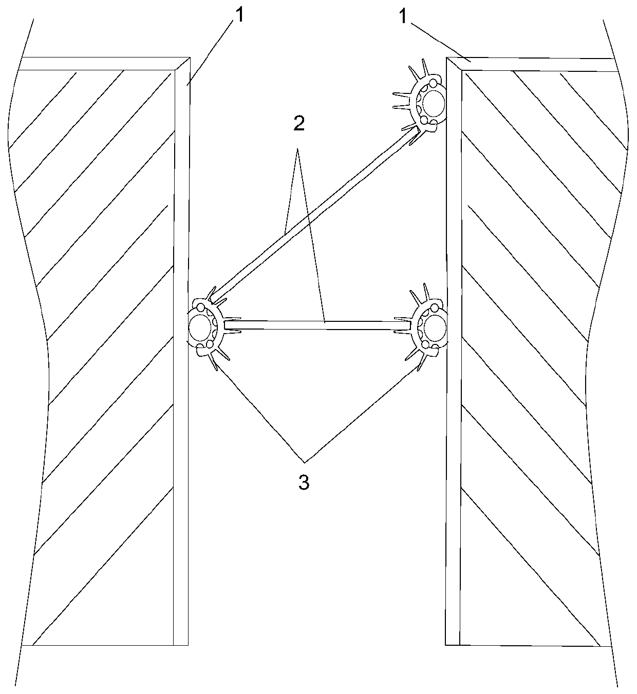
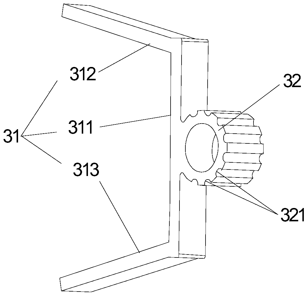
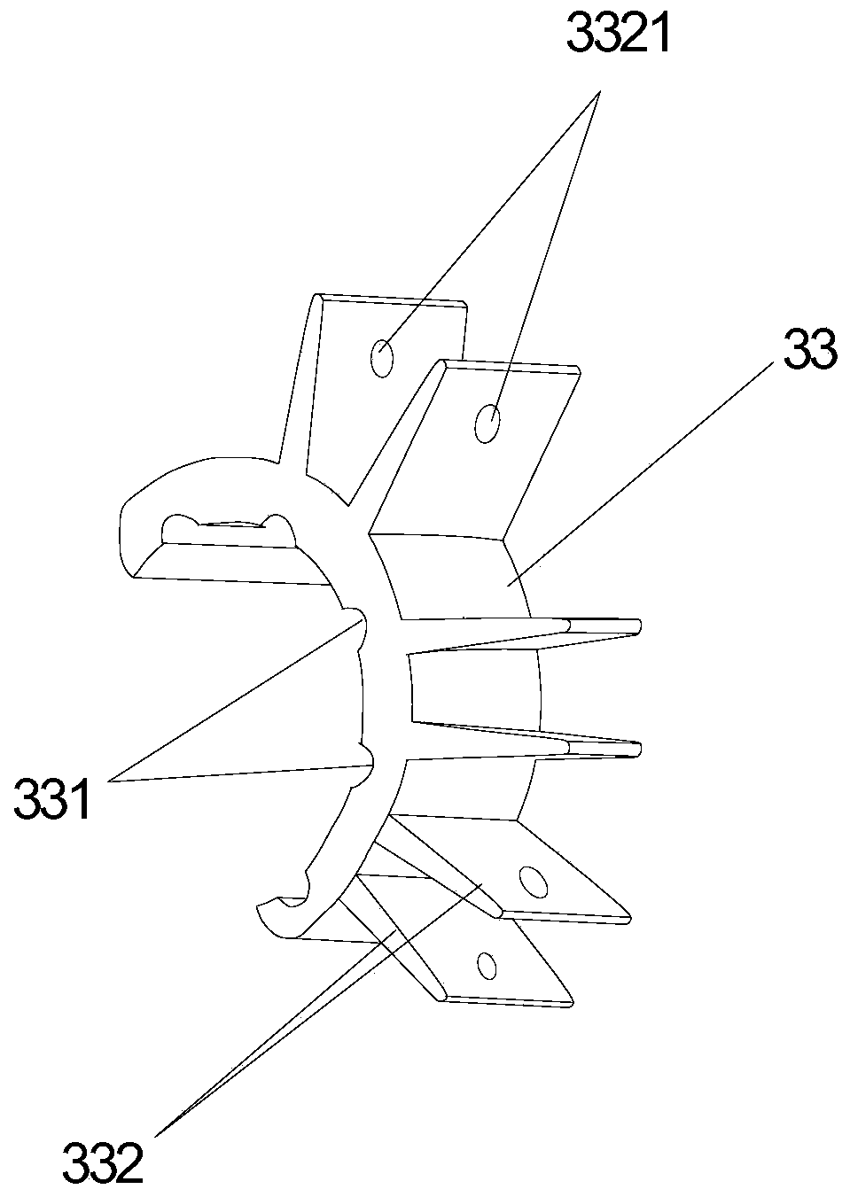
The embodiment of the invention discloses a steel structure and concrete pre-buried connection structure. The steel structure and concrete pre-buried connection structure comprises a concrete body, asteel structure body and a connecting part pre-buried in the concrete body, the connecting part comprises a connecting body, a positioning seat, a movable clamping claw sleeve, a plurality of first bolts and a plurality of first nuts, the connecting body is fixedly connected with the concrete body, the positioning seat is fixedly connected with the connecting body, the movable clamping claw sleevesurrounds the positioning seat and is rotatably connected to the positioning seat in a sleeving mode, all the first bolts are inserted in positioning inserting holes formed by the positioning seat and the movable clamping claw sleeve, all the first nuts sleeve all the first bolts, the first nuts and the first bolts are arranged on the two sides of the positioning inserting holes in an abutting mode correspondingly, the movable clamping claw sleeve is provided with a plurality of clamping claws, and the steel structure body is fixedly connected with the clamping claws. Through the steel structure and concrete pre-buried connection structure, the steel structure body and the concrete body are detachably connected in multi-angle mode, the structure is simple, and applicability is high.

Description

technical field [0001] The embodiments of the present invention relate to the field of building installation, in particular to a pre-embedded connection structure between a steel structure and concrete. Background technique [0002] Steel structure buildings have the advantages of light weight, high strength, excellent plastic toughness, etc., and are widely used in building structure design. The steel structure has a large bearing capacity, and the connection between the steel structure and the concrete structure determines the stability of the structure, thereby ensuring the safety and practicality of the building structure. [0003] The inventor of the present application found that in the prior art, the connection between the steel structure and the concrete structure is generally embedded in the concrete through steel embedded parts, and then the connection between the steel structure and the embedded parts is realized by welding. Embedded parts and concrete are direct...

Claims


Application Information

Patent Timeline
IPC IPC(8): E04B1/41
CPCY02E10/50
Inventor 胡宝山刘喜林王双
Owner SHANGHAI ZHIPING FOUNDATION ENG CO LTD
Learn More