
Vertical shaft tidal current energy power generation device

A technology of power generation device and tidal current energy, which is applied in ocean energy power generation, hydropower generation, engine components, etc., can solve the problems of low speed, large starting torque, low maintenance cost, etc., achieve high power, improve output power, restrain the terminal The effect of the eddy current

Pending Publication Date: 2019-06-07
CHINA UNIV OF PETROLEUM (EAST CHINA)
View PDF0 Cites 9 Cited by
  • Summary
  • Abstract
  • Description
  • Claims
  • Application Information

AI Technical Summary

Problems solved by technology

[0003] Tidal current energy generation devices can be roughly divided into two categories: horizontal axis tidal current energy generation devices and vertical axis tidal current energy generation devices. Vertical axis tidal current energy generation devices are more and more popular because of their simple structure, no need for additional convection devices, and low maintenance costs. Attracted and favored by scholars at home and abroad, the current vertical axis tidal current energy generation devices are roughly divided into two categories: resistance type vertical axis tidal current energy generation devices and lift type vertical axis tidal current energy generation devices, resistance type vertical axis tidal current energy generation devices The starting torque is small and easy to self-start, but the speed is low and the power generation is low; the lift type vertical axis tidal current energy generator has a high speed and high power generation, but the starting torque is large and it is not easy to self-start. A device capable of effectively combining the two

Method used


Image

  • Vertical shaft tidal current energy power generation device
  • Vertical shaft tidal current energy power generation device
  • Vertical shaft tidal current energy power generation device

Examples


Embodiment Construction

[0029] The following will clearly and completely describe the technical solutions in the embodiments of the present invention with reference to the accompanying drawings in the embodiments of the present invention. Obviously, the described embodiments are only some, not all, embodiments of the present invention. Based on the embodiments of the present invention, all other embodiments obtained by persons of ordinary skill in the art without making creative efforts belong to the protection scope of the present invention.

[0030] The terms "first", "second", and the like in the description and claims of the present invention and the above drawings are used to distinguish similar objects, and are not necessarily used to describe a specific sequence or sequence. It is to be understood that the data so used are interchangeable under appropriate circumstances such that the embodiments of the invention described herein are, for example, capable of practice in sequences other than thos...


PUM


Abstract

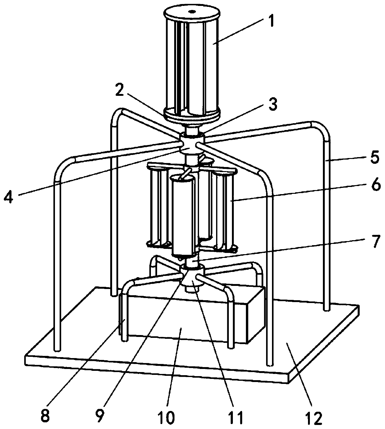
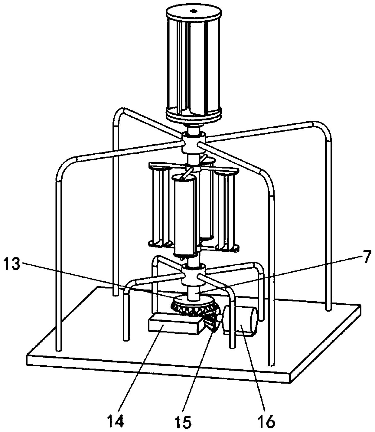
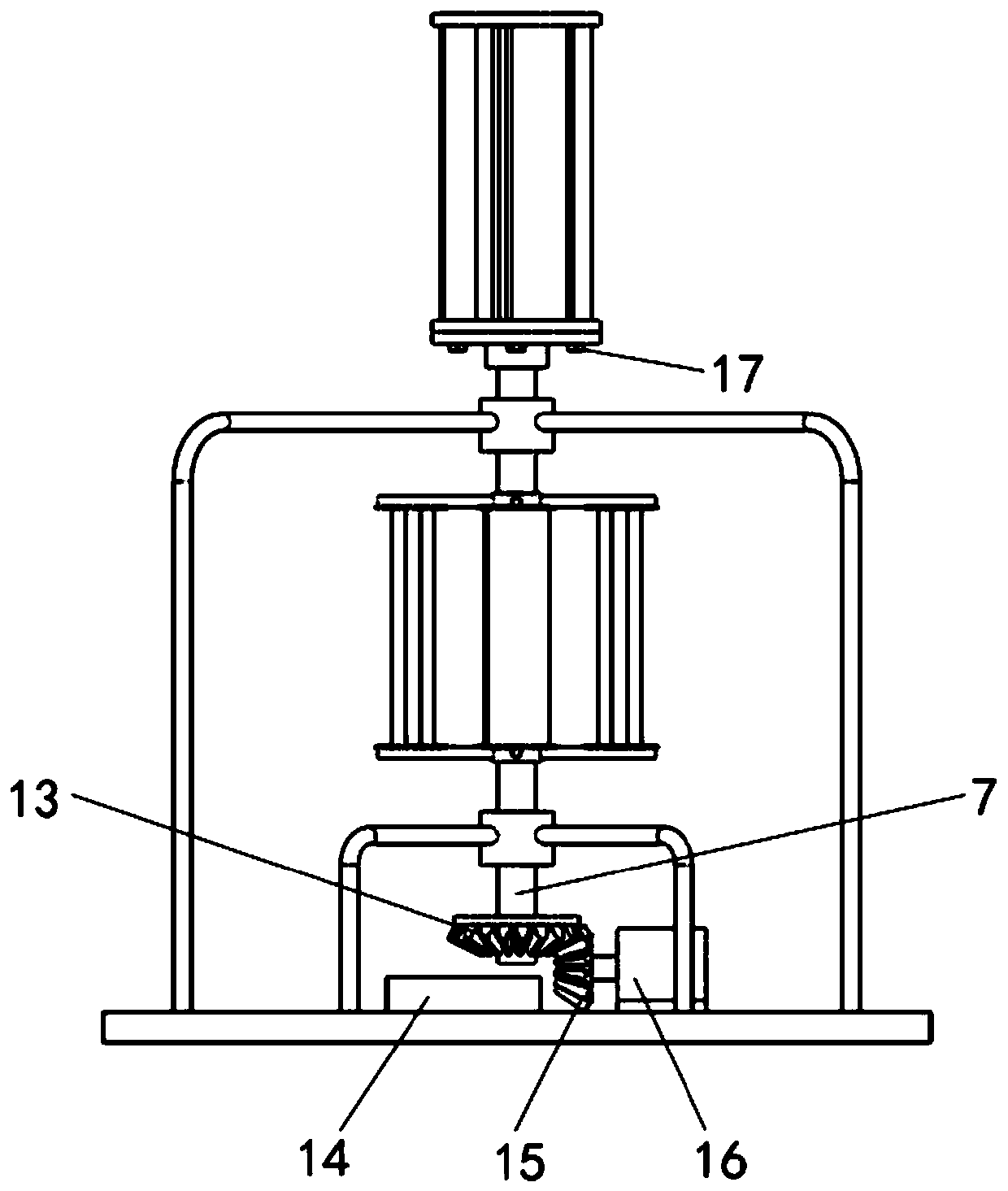
The invention relates to a tidal current energy power generation device, in particular to a vertical shaft tidal current energy power generation device. The vertical shaft tidal current energy power generation device comprises an auxiliary starting water turbine, a connecting block, a main water turbine, a rotating shaft, a first bevel gear, a control cabinet, a second bevel gear, a generator, a connecting and disconnecting device and the like. When the seawater flow speed is low, a resistance-type auxiliary starting water turbine auxiliary starts a lifting-type main water turbine, so that themain water turbine rotates even when the seawater flow speed is low, and the overall power generation output is improved; when the seawater flow speed is high, the resistance-type auxiliary startingwater turbine and the lifting-type main water turbine independently operate without dragging the lifting-type main water turbine, and the main water turbine independently drives the rotating shaft torotate to generate electricity, so that the power generation output is greatly improved; and the main water turbine adopts a double-layer blade with an end plate, the end plate can effectively restrain vortex at the end portion of the blade and improve power output, the torque of the double-layer blade is larger than the torque of a single-layer blade, and the power is higher.

Description

technical field [0001] The invention relates to a tidal current energy generating device, in particular to a vertical axis tidal current energy generating device. Background technique [0002] There is abundant energy in the ocean. At present, the development of ocean energy is not very deep. For ocean energy power generation, because it is safe, reliable and pollution-free, it has a good development prospect. If the ocean energy can be effectively and fully developed and utilized , will effectively alleviate the current energy crisis and climate warming problems. Tidal current energy is a kind of ocean energy and has good development prospects. Compared with wind power generation, it has the following advantages: the density of seawater is more than 800 times that of air, and the energy density is concentrated; the tidal flow has strong regularity , is predictable. [0003] Tidal current energy generation devices can be roughly divided into two categories: horizontal axis...

Claims


Application Information

Patent Timeline
IPC IPC(8): F03B13/26F03B3/12
CPCY02E10/20Y02E10/30
Inventor 李增亮王萌范梦浩都晓鹏孙召成
Owner CHINA UNIV OF PETROLEUM (EAST CHINA)
Learn More