
Anti-shake structure, anti-shake system and camera device

A technology of accommodating cavity and end pins, which is applied in the field of cameras, and can solve problems such as the complex internal structure of the anti-shake structure

Pending Publication Date: 2019-06-07
SHANGHAI SMA TECH CO LTD
View PDF0 Cites 24 Cited by
  • Summary
  • Abstract
  • Description
  • Claims
  • Application Information

AI Technical Summary

Problems solved by technology

[0009] The main purpose of the present invention is to provide an anti-shake structure, an anti-shake system and an imaging device, so as to solve the problem that the internal structure of the anti-shake structure is complicated in the prior art

Method used


Image

  • Anti-shake structure, anti-shake system and camera device
  • Anti-shake structure, anti-shake system and camera device
  • Anti-shake structure, anti-shake system and camera device

Examples


Embodiment 1

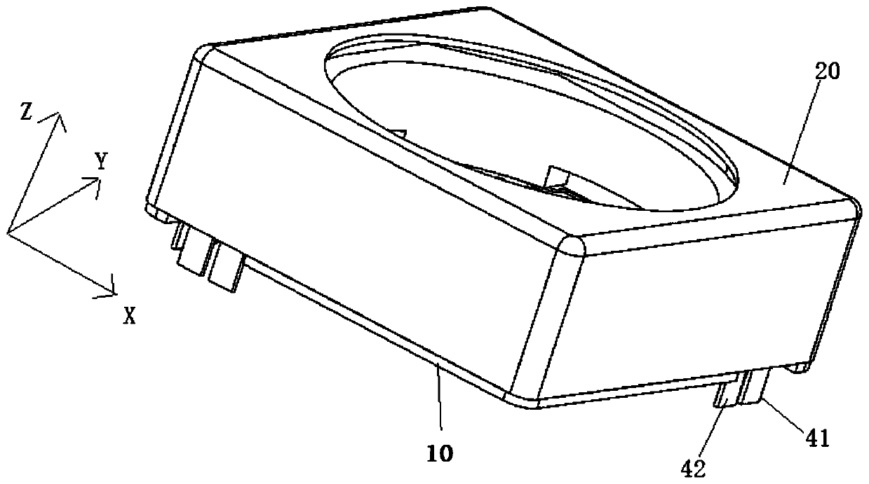
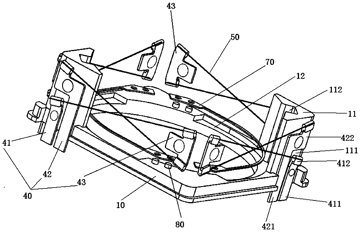
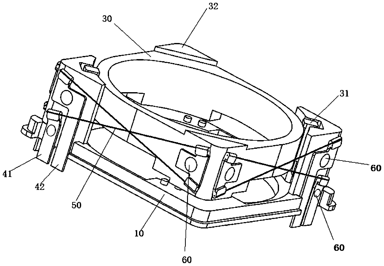
[0053] Such as Figure 1 to Figure 5 As shown, the anti-shake structure in this application includes a base 10 , a housing 20 , a lens support 30 , at least four sets of PIN pin structures 40 , a plurality of SMA wires 50 and a spring 70 . The housing 20 is covered on the outside of the base 10 and forms an accommodating cavity between the two; the lens support body 30 is disposed in the accommodating cavity; at least four groups of PIN pin structures 40 are located in the accommodating cavity, and each of the base 10 At least one set of PIN terminal pin structures 40 are correspondingly arranged on the sides, and each set of PIN terminal pin structures 40 includes a first PIN terminal pin 41, a second PIN terminal pin 42 and a pressing piece 43, and the first PIN terminal pin 41 and the second PIN terminal feet 42 are independently arranged on the base 10, and the pressing piece 43 is arranged on the lens support body 30; each group of PIN terminal foot structures 40 is corre...

Embodiment 2

[0092] The difference from Embodiment 1 is that the PIN pin structure 40 is integrally embedded and molded by means of INSERT MOLDING.

[0093] Optionally, at least a part of the pressing piece 43 is embedded in the lens support body 30 , and the connection end of the pressing piece 43 is located outside the lens support body 30 .

[0094] Optionally, at least a part of the first PIN terminal 41 is embedded in the base 10 , and the connection end of the first PIN terminal 41 is located outside the base 10 .

[0095] Optionally, at least a part of the second PIN terminal 42 is embedded in the base 10 , and the connection end of the second PIN terminal 42 is located outside the base 10 .

[0096] exist Figure 6 to Figure 8 In the specific embodiment shown, the pressing piece 43 is embedded in the lens support body 30 in an integral molding manner and the part connected to the SMA wire 50 is exposed, and the first PIN terminal pin 41 and the second PIN terminal pin 42 are conne...


PUM


Abstract

The invention provides an anti-shake structure, an anti-shake system and a camera device. The anti-shake structure comprises a base, a shell, a lens supporting body, at least four groups of PIN end foot structures and a plurality of SMA wires, wherein the shell is arranged outside the base in a covering mode, and an accommodating cavity is formed between the shell and the base; the lens supportingbody is arranged in the accommodating cavity; the at least four groups of PIN end foot structures are positioned in the accommodating cavity, and at least one group of the PIN end foot structures arecorrespondingly arranged at each side edge of the base; each group of the PIN end foot structures comprises a first PIN end foot, a second PIN end foot and a pressing sheet; the first PIN end feet and the second PIN end feet are arranged on the base in an independent with each other mode; and the pressing sheets are arranged on the lens supporting body; and each group of the PIN end foot structures are correspondingly connected with two SMA wires which are arranged in a crossing way, wherein one SMA wire connects the first PIN end feet with the pressing sheets, and the other SMA wire connectsthe second PIN end feet with the pressing sheets. The anti-shake structure, the anti-shake system and the camera device solve the problem of complex internal structure of the anti-shake structure inthe prior art.

Description

technical field [0001] The present invention relates to the field of camera technology, in particular to an anti-shake structure, an anti-shake system and a camera device. Background technique [0002] The photos taken by electronic devices such as mobile phones sometimes appear blurry during the shooting process, that is, the captured pictures are not clear enough, and ghosting or blurring occurs. These reasons, except for occasional out-of-focus (that is, the camera lens fails to focus normally), are largely caused by slight jitters when the scene is exposed. Generally speaking, this very slight jitter phenomenon often occurs under handheld conditions. In this context, proposals for OIS (Optical Image Stabilization System) optical image stabilization functions have also increased, and micro-optical image stabilization technology has gradually been adopted by various high-end mobile phones, hoping to effectively reduce blur in low-light environments The probability of tak...

Claims


Application Information

Patent Timeline
IPC IPC(8): G03B5/00H04N5/232
Inventor 王建华张晓良
Owner SHANGHAI SMA TECH CO LTD
Learn More