Explosion-proof structure of an underground inspection robot

An inspection robot and explosion-proof structure technology, applied in the field of inspection robots, can solve the problems of increased maintenance costs, affecting moving speed, high cost, etc., and achieve the effect of improving the ability to resist explosions, avoid blocking the movement of rollers, and enhance hardness and rigidity

Active Publication Date: 2020-12-18
安徽玄离智能科技股份有限公司
View PDF12 Cites 0 Cited by
  • Summary
  • Abstract
  • Description
  • Claims
  • Application Information

AI Technical Summary

Problems solved by technology

[0002] my country has a large amount of coal storage, most of the coal mines are high gas, the mining environment is harsh, and the risk is high. The death rate of coal mine production per million tons has always been high. It is particularly important. At present, the monitoring of environmental safety parameters in coal mines is divided into two methods: manual monitoring and automatic monitoring. In view of the harsh working environment and poor lighting in the underground, manual monitoring is not conducive to inspection personnel and timely detection of problems. At the same time, there are workers The labor intensity is high, and the detection effect is unstable; the existing automatic monitoring system, due to the long distance of the underground roadway and many monitoring points, makes the automatic monitoring system complex, with a wide variety of monitoring equipment, a large number, and high cost. With the development of robot technology, robots It has been widely used in coal mine production operations, mine accident handling and rescue, and coal mine daily monitoring and maintenance.
[0003] However, the explosion-proof function of the general underground inspection robot itself is not very good, it is easy to cause great damage to itself, the maintenance cost increases, and the ability of the inspection robot to climb over obstacles is not very good, which affects the moving speed

Method used


Image

  • Explosion-proof structure of an underground inspection robot
  • Explosion-proof structure of an underground inspection robot
  • Explosion-proof structure of an underground inspection robot

Examples


Embodiment 1

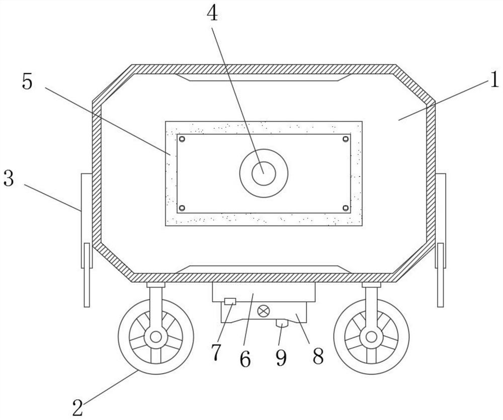
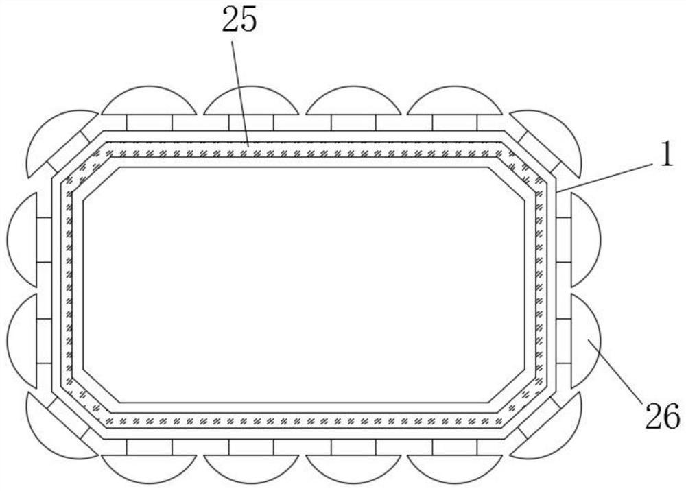
[0028] Such as figure 1 , figure 2 and Figure 4 As shown, an explosion-proof structure of an underground inspection robot includes an inspection robot housing 1, a roller 2 and an infrared camera 4, the roller 2 is located at the bottom of the inspection robot housing 1, and the infrared camera 4 is located on the surface of the inspection robot housing 1 On one side, an explosion-proof box 3 is welded on the bottom side of the inspection robot shell 1. The explosion-proof box 3 is provided with four groups. The inside of the explosion-proof box 3 is provided with a metal explosion-proof plate 15. Pulleys 16 are installed on both sides of the metal explosion-proof plate 15. The explosion-proof box 3 Slide rails 17 are welded on both sides of the inner wall, and the metal explosion-proof plate 15 is slidably connected to the slide rail 17 through the pulley 16. The inspection robot shell 1 is filled with a barrier explosion-proof metal material layer 25, and the inspection r...

Embodiment 2

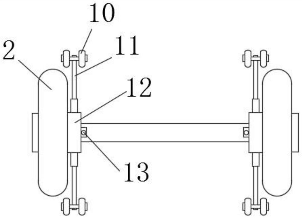
[0031] Such as figure 1 and image 3 As shown, the infrared camera 4 is provided with an explosion-proof glass 5 outside, and the explosion-proof glass 5 is fixedly connected with the inspection robot housing 1, and the bottom of the inspection robot housing 1 is fixedly connected with the sampling box 6, and an air pump 8 is installed at the bottom of the sampling box 6. One end of the air pump 8 is fixedly connected to the check valve 7, and the other end of the air pump 8 is fixedly connected to the air inlet 9. The air pump 8 communicates with the sampling box 6 through the check valve 7. A bearing 12 is installed on one side of the roller 2, and the outside of the bearing 12 Ring is provided with electric telescopic rod 11, and electric telescopic rod 11 is provided with nine groups, and electric telescopic rod 11 one end is equipped with explosion-proof wheel-10, and bearing 12 side is provided with remote control switch 13, air pump 8, electric telescopic rod 11 and Th...

Embodiment 3

[0034] Such as Figure 5 As shown, gas springs 19 are inlaid on both sides of the exterior of the inspection robot shell 1, and one end of the gas spring 19 is fixedly connected to the explosion-proof partition 120. One side of the pad 22 is fixedly connected to the second explosion-proof partition 21, and the inside of the foldable fireproof pad 22 is filled with a laminated rubber shock-isolation support 23, and the outer surface of the laminated rubber shock-isolation support 23 is bonded with a fireproof cloth 24.

[0035] In this embodiment, the gas spring 19 and the laminated rubber vibration-isolation support 23 are provided to effectively reduce the vibration generated by the shell 1 of the inspection robot when an explosion occurs.

[0036]It should be noted that the present invention is an explosion-proof structure of an underground inspection robot. When working, the device is connected to a mobile power supply. The inspection robot housing 1 takes pictures of the u...


PUM


Abstract

The invention discloses an anti-explosion structure of a downhole polling robot. The anti-explosion structure comprises a polling robot shell, rollers and an infrared camera. The rollers are located at the bottom of the polling robot shell, the infrared camera is located on one side of the surface of the polling robot shell, and anti-explosion boxes are welded to the side faces of the bottom of the polling robot shell. Through the arrangement of a blocking anti-explosion metal material layer and nickel-based alloy semicircular blocks, the hardness and the rigidity of the polling robot shell are improved; through the arrangement of the anti-explosion boxes and metal anti-explosion plates, the anti-explosion performance of the polling robot shell is improved, and damage of downhole emergencies to the polling robot shell is reduced; through the arrangement of a sucking pump and a check valve, downhole air is sampled, and the downhole air can be conveniently detected; through the arrangement of electric telescopic rods and first anti-explosion wheels, the situation that barriers block movement of the rollers is effectively avoided; and through the arrangement of air springs and a laminated rubber shock insulating support, vibration generated by the polling robot shell is effectively reduced when explosions happen.

Description

technical field [0001] The invention relates to a patrol robot, in particular to an explosion-proof structure of an underground patrol robot. Background technique [0002] my country has a large amount of coal storage, most of the coal mines are high gas, the mining environment is harsh, and the risk is high, and the death rate of coal mine production per million tons has always been high. It is particularly important. At present, the monitoring of environmental safety parameters in coal mines is divided into two methods: manual monitoring and automatic monitoring. In view of the harsh working environment and poor lighting in the underground, manual monitoring is not conducive to inspection personnel and timely detection of problems. At the same time, there are workers The labor intensity is high and the detection effect is unstable; the existing automatic monitoring system, due to the long distance of the underground roadway and many monitoring points, makes the automatic mon...

Claims


Application Information

Patent Timeline
Patent Type & Authority Patents(China)
IPC IPC(8): B25J11/00B25J19/00B25J19/06G01N1/22
Inventor 郭延达
Owner 安徽玄离智能科技股份有限公司
Why Eureka
Try Eureka