
Automobile anti-collision beam capable of reducing collision kinetic energy

A technology of anti-collision beams and automobiles, applied in the direction of bumpers, etc., can solve the problems of reduced safety, single protective measures, and inability to play a buffer, so as to reduce hard damage and increase the effect of safety protection

Pending Publication Date: 2019-06-11
安徽彤上智能科技有限公司
View PDF12 Cites 2 Cited by
  • Summary
  • Abstract
  • Description
  • Claims
  • Application Information

AI Technical Summary

Problems solved by technology

However, due to the relatively simple protective measures, it is easy to deform quickly when an accident occurs and is impacted, and cannot play a buffer role, reducing safety and low protection.

Method used

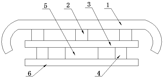

Image

  • Automobile anti-collision beam capable of reducing collision kinetic energy
  • Automobile anti-collision beam capable of reducing collision kinetic energy
  • Automobile anti-collision beam capable of reducing collision kinetic energy

Examples


Embodiment 1

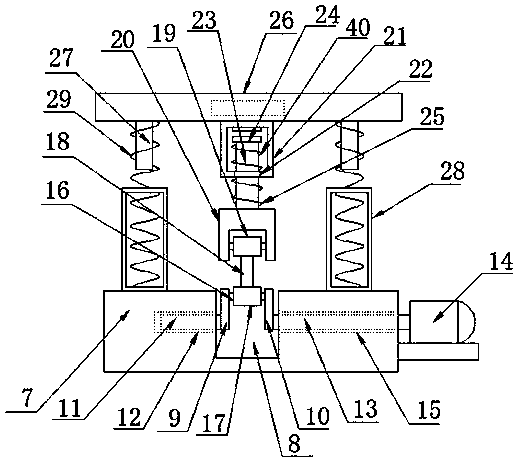
[0023] Such as Figure 1-2 As shown, an automobile anti-collision beam for reducing impact kinetic energy according to an embodiment of the present invention includes an anti-collision beam beam 1, and the bottom end of the anti-collision beam beam 1 is provided with a plurality of evenly distributed energy absorbing boxes 2, so The bottom end of the energy absorbing box 2 is provided with a load-bearing plate 3, the bottom end of the load-bearing plate 3 is provided with buffer components 4 symmetrically on both sides, and the middle of the bottom end of the load-bearing plate 3 is provided with a damping mechanism 5. 4 and the bottom end of the damping mechanism 5 are connected to the mounting plate 6. The damping mechanism 5 includes a base plate 7 at the top of the mounting plate 6, and a slot 8 is provided in the middle of the top of the base plate 7. The slot 8 is provided with a rocker 9 and a rocker 2 10 respectively. One end of the rocker 9 away from the rocker 2 10 is...

Embodiment 2

[0026] Such as figure 2 As shown, the inner wall of the cavity of the sleeve 21 away from the through hole 22 is provided with an elastic block adapted to the limiting plate 24.

[0027] Such as figure 2 As shown, the bottom end of the rotating electric machine 14 is provided with a base, and one side of the base is connected to the substrate 7.

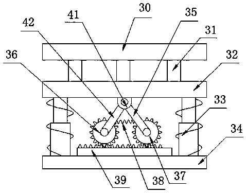
[0028] Such as image 3 As shown, the buffer assembly 4 includes a second movable plate 30 connected to the bottom end of the load-bearing plate 3, and the bottom end of the second movable plate 30 is provided with a number of uniformly distributed rubber blocks 31. The bottom end is connected to the third movable plate 32, the bottom end of the third movable plate 32 is provided with telescopic components 33 symmetrically on both sides, and the bottom end of the telescopic component 33 is connected to the second base plate 34 located at the top of the mounting plate 6.

[0029] Such as image 3 As shown, the telescopic assembly 33 is com...


PUM


Abstract

The invention discloses an automobile anti-collision beam capable of reducing collision kinetic energy. The automobile anti-collision beam comprises an anti-collision beam cross beam. Multiple evenly-distributed energy absorption boxes are arranged at the bottom end of the anti-collision beam cross beam, a bearing plate is arranged at the bottom ends of the energy absorption boxes, buffer assemblies are symmetrically arranged on the two sides of the bottom end of the bearing plate, a damping mechanism is arranged in the middle of the bottom end of the bearing plate, and the bottom end of the buffer assembly and the bottom end of the damping mechanism are connected with a mounting plate. The damping mechanism comprises a first base plate located at the top end of the mounting plate, an opengroove is formed in the middle position of the top of the first base plate, a first rocker and a second rocker are arranged in the open groove, the end, away from the second rocker, of the first rocker is connected with a first rotary shaft, and the first rotary shaft stretches into the first base plate. The automobile anti-collision beam has the beneficial effects that through the arrangement ofthe buffer assembly and the damping mechanism, impact force can be effectively dispersed and buffered and decomposed, the impact force is weakened, losses of a user are minimized while hard injuriesof vehicles and staff are reduced, and the safety protection effect is improved.

Description

Technical field [0001] The invention relates to the field of anti-collision beams, in particular to an automobile anti-collision beam that reduces the kinetic energy of impact. Background technique [0002] With the improvement of people's quality of life, cars are becoming more and more popular, and people's awareness of preventing traffic accidents is also increasing year by year, so every car will be installed with anti-collision beams. At present, most of the automobile anti-collision beams on the market use simple beams or energy-absorbing boxes embedded in the beams to buffer and absorb the impact of the collision. However, due to the relatively single protective measures, it is easy to quickly deform when an accident is impacted, and cannot play a buffering role, reducing safety and low protection. [0003] For the problems in related technologies, no effective solutions have yet been proposed. Summary of the invention [0004] In view of the problems in the related art, ...

Claims


Application Information

Patent Timeline
Patent Type & Authority Applications(China)
IPC IPC(8): B60R19/36
Inventor 杨知宝
Owner 安徽彤上智能科技有限公司
Learn More