
Beam tube type light optical cable

A bundle-type, light-weight technology, applied in the field of optical cable manufacturing, can solve the problems of reducing PE sheath, insulation outer wall cracks, etc., to improve work performance, improve bending resistance and damage resistance, and ensure stable work performance.

Inactive Publication Date: 2015-09-16
成都亨通光通信有限公司
View PDF7 Cites 0 Cited by
  • Summary
  • Abstract
  • Description
  • Claims
  • Application Information

AI Technical Summary

Problems solved by technology

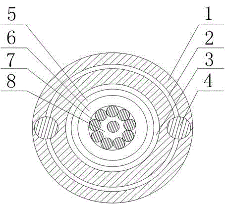
Aiming at the problem in the prior art that the ribbon optical cable is prone to breakage or its insulating outer wall is prone to cracks, the present invention firstly arranges two copper wires and a plurality of equidistantly spaced annular rings in the PE sheath along its axis. Reinforcing ribs, and multiple annular reinforcing ribs are sleeved on two copper wires along the radial direction of the PE sheath, so that a tubular support skeleton is formed in the PE sheath, and then the central sleeve is fixed in the middle of the PE sheath At the same time, ensure that the outer circumferential wall of the central sleeve is in close contact with the inner wall of the PE sheath. After placing multiple optical fibers in the central sleeve, fill the central sleeve with fiber paste, so that the inner wall of the PE sheath is fully supported. That is, the processing of the optical cable is completed; and during the use of the present invention, when encountering a corner or a region with a large bending range, the PE sheath is deformed and twisted, and at this time, the parts located inside the PE sheath are squeezed against each other , and the tubular skeleton formed by the copper wires and reinforcing ribs in the PE sheath makes corresponding deformations according to the torsional stress received, so as to buffer the stress effect transmitted from the PE sheath to the casing and reduce the severe deformation of the PE sheath to At the same time, the gaps between multiple optical fibers in the central sleeve are filled with fiber paste, which can fix the sleeve and optical fibers to a certain extent and at the same time play a role of mechanical buffering, and finally realize the guarantee of the fiber optic cable. The structure is compact, and the purpose of improving the bending resistance and damage resistance of the optical cable

Method used


Image

  • Beam tube type light optical cable

Examples


Embodiment 1

[0019] Such as figure 1 As shown, this embodiment includes a PE sheath 1 and a central sleeve 6 arranged in the middle of the PE sheath 1, the central sleeve 6 is filled with fiber paste 8, and a plurality of optical fibers 7 are fixed in the central sleeve 6 In the PE sheath 1, two copper wires 4 are symmetrically arranged along its axis, and also include a plurality of annular reinforcing ribs 2 arranged in the PE sheath 1, and the plurality of reinforcing ribs 2 are arranged along the PE sheath. The sleeve 1 is sleeved on two copper wires 4 at equal radial intervals. In view of the problems in the prior art that the ribbon optical cable is prone to breakage or its insulating outer wall is prone to cracks, the present invention firstly arranges two copper wires 4 symmetrically along its axis in the PE sheath 1 and multiple equidistantly spaced ones. The annular reinforcing rib 2, and a plurality of annular reinforcing ribs 2 are sleeved on two copper wires 4 along the radia...


PUM


Abstract

The invention discloses a beam tube type light optical cable comprising a PE sheath and a central bushing which is arranged at the middle part of the PE sheath. Fiber paste is filled in the central bushing, and multiple optical fibers are fixed in the central bushing. Two copper wires are symmetrically arranged in the PE sheath along the axis of the PE sheath. The beam tube type light optical cable also comprises multiple annular reinforcing ribs which are arranged in the PE sheath. The multiple reinforcing ribs equidistantly sleeve the two copper wires in a spacing way along the radial direction of the PE sheath. The PE sheath deforms and warps when encountering a corner or a regional section with higher degree of bending, all the parts arranged in the internal part of the PE sheath mutually extrude at the time, and a tubular framework formed by the copper wires and the reinforcing ribs in the PE sheath correspondingly deforms according to the affected torsional stress so as to buffer the stress effect of the PE sheath transmitted to the bushing and reduce the probability of severe deformation and even damage to the PE sheath.

Description

technical field [0001] The invention relates to the field of optical cable manufacturing, in particular to a bundle tube type light optical cable. Background technique [0002] In daily life, optical fibers are used for long-distance information transmission because the loss of light in optical fibers is much lower than that of electricity in wires. Most optical fibers must be covered by several layers of protective structures before use. The coated cable is called an optical cable. The protective layer and insulating layer on the outer layer of the optical fiber can prevent the surrounding environment from harming the optical fiber, such as water, fire, electric shock, etc. . [0003] The bundle tube type has a simple structure, simple manufacturing process, better protection of optical fibers than other optical cables, and the bundle tube type optical cable has the advantages of lateral pressure resistance, small cable cross-section, light weight, etc., and the number of ...

Claims


Application Information

Patent Timeline
Patent Type & Authority Applications(China)
IPC IPC(8): G02B6/44
CPCG02B6/4432G02B6/4429
Inventor 孙义兴王耀明许建国彭志勇刘东李涛
Owner 成都亨通光通信有限公司
Learn More