Vertical drive arc-shaped gate bar valve device of chute

A valve device and arc-shaped technology, which is applied in the field of vertically driven arc-shaped grid rod valve devices, can solve the problems of manual operation of a single rod valve, failure to close, timely material cut-off and flow control, etc., to save human resources Low cost, small occupation of horizontal space, good for production arrangement

Pending Publication Date: 2019-06-11
MCC NORTH (DALIAN) ENG TECH CO LTD
View PDF0 Cites 0 Cited by
  • Summary
  • Abstract
  • Description
  • Claims
  • Application Information

AI Technical Summary

Problems solved by technology

At present, in the practical application of production, the widely used valve device is the flat gate. The problem existing in the use of the flat gate is that the resistance to be overcome when the flat gate is closed is very large, and sometimes it cannot be closed due to blockage of block materials.
However, a single rod valve requires manual operation. It is time-consuming and labor-intensive to knock the rods into the chute one by one or pull them out from the chute, and the material cannot be cut off and flow controlled in time, which affects production; grouped rod valves are usually driven by The device drives the insertion and extraction of the group of rod valves, which overcomes the disadvantages of manual operation, but because the stroke of the rods is usually greater than the width of the chute, and the length of the push rod of the driving device, the group of rod valves needs to occupy Large horizontal space, which is the main reason for restricting the application of group rod valves in production, because usually there is not enough horizontal space in the process design for arranging group rod valves and their driving devices; in addition, As the protruding length of the group of rod valves increases, the supporting reaction force of the horizontal slideway of the group of rod valves increases accordingly, resulting in an increase in horizontal resistance, which requires a greater driving force, thereby increasing costs and energy consumption

Method used


Image

  • Vertical drive arc-shaped gate bar valve device of chute
  • Vertical drive arc-shaped gate bar valve device of chute
  • Vertical drive arc-shaped gate bar valve device of chute

Examples


Embodiment Construction

[0022] The present invention will be further described below in conjunction with accompanying drawing.

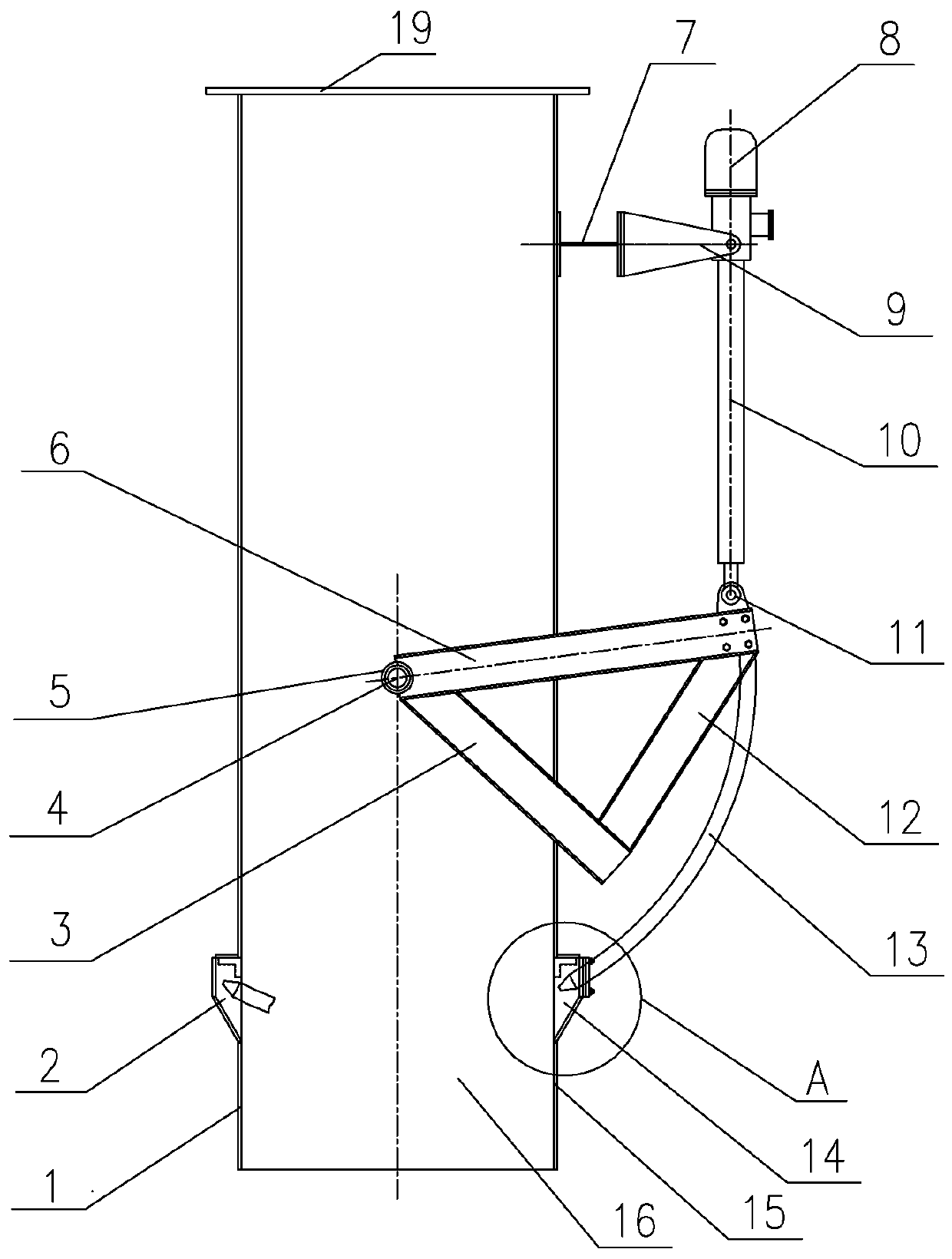
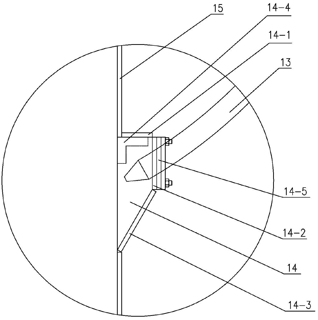
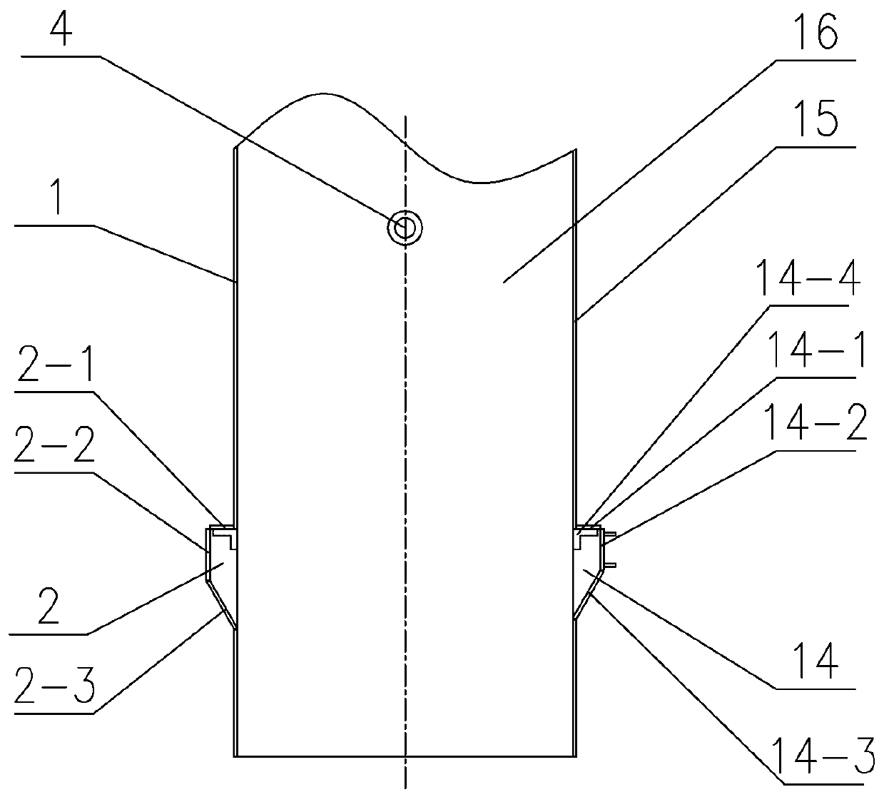
[0023] Such as Figure 1-Figure 8 As shown, a vertically driven arc-shaped grid rod valve device for a chute of the present invention includes a chute composed of a top flange 19, a front side plate 16, a rear side plate, a right side plate 15 and a left side plate 1. The top of the chute is fixed to the bottom of the ore bin by its top flange 19 bolts. It is characterized in that: an arc-shaped grid rod valve device is arranged on the lower part of the right side plate 15 of the chute, and the arc-shaped grid rod valve device includes an arc-shaped grid rod valve device. Grid rod valve and hydraulic system, the arc-shaped grid rod valve includes a set of arc-shaped claw drill rods 13, a beam 17 and two triangular swing arms; The outer sides are respectively welded with trunnions 4, and the trunnions 4 are symmetrically located on the center vertical line of the front side...


PUM


Abstract

The invention relates to a vertical drive arc-shaped gate bar valve device of a chute. The vertical drive arc-shaped gate bar valve device of the chute comprises a chute body. The vertical drive arc-shaped gate bar valve device of the chute is characterized in that the arc-shaped gate bar valve device is arranged on the lower part of the chute body and an arc-shaped claw drill bar channel is formed in the lower part of the chute body, the arc-shaped gate bar valve device comprises an arc-shaped gate bar valve and a hydraulic system, the arc-shaped gate bar valve comprises an arc-shaped claw drill bar, a beam and two triangular swinging arms, the claw drill bar is perpendicularly and fixedly connected to the beam, two shaft sleeves of the upper ends of the two triangular swinging arms are separately and rotatably connected with trunnions of the front side plate and the rear side plate of the chute body, and the lower ends of the two triangular swinging arms are connected with the two ends of the beam in a bolt mode; and the hydraulic system comprises a hydraulic station, a hydraulic oil cylinder and a fixed bracket, the fixed bracket is arranged on the upper part of the right side plate of the chute body, the hydraulic oil cylinder is hinged to the fixed bracket, and a telescopic rod of the hydraulic oil cylinder is hinged to the beam in a driving mode. The vertical drive arc-shaped gate bar valve device of the chute has the advantages of simple structure, horizontal space-saving, convenient mounting, hydraulic driving a switch of a valve, high efficiency, shortened time andlabor saving, and fast operation.

Description

technical field [0001] The invention belongs to the technical field of valves used for flow control of a chute, in particular to a vertically driven arc grid rod valve device for a chute. Background technique [0002] In metallurgy, mining and other industries, chutes are often used to divert or transfer bulk materials, and sometimes it is necessary to cut off or control the flow of bulk materials. Therefore, it is necessary to install a valve device in the middle of the chute. At present, in the practical application of production, the widely used valve device is the flat gate. The problem existing in the use of the flat gate is that the resistance to be overcome when the flat gate is closed is very large, and sometimes it cannot be closed due to blockage of block materials. In order to overcome this deficiency, combined with the characteristics of bulk materials, rod valves will be used instead of flat gates in production. Rod valves are divided into single rod valves and...

Claims


Application Information

Patent Timeline
Patent Type & Authority Applications(China)
IPC IPC(8): B65G11/20
Inventor 杨庆林杨海龙王星亮王欢
Owner MCC NORTH (DALIAN) ENG TECH CO LTD
Why Eureka
Try Eureka