
Washing machine

A technology of washing machines and washing tubs, which is applied to other washing machines, washing machines with containers, washing devices, etc., and can solve the problems of wasting water, the chamber cannot be cleaned and polluted, and the water cannot be completely discharged.

Active Publication Date: 2019-06-11
QINGDAO HAIER WASHING MASCH CO LTD +2
View PDF5 Cites 3 Cited by
  • Summary
  • Abstract
  • Description
  • Claims
  • Application Information

AI Technical Summary

Problems solved by technology

In the washing process, the washing bucket is connected with the outer tub through the dehydration hole provided on it, so that the inside of the washing bucket and the outer tub are filled with water, so there are three problems in the conventional washing machine in the prior art: first, waste Water, in the actual work, only the water in the washing bucket is needed; second, the bacteria grow, the water at the connection between the washing bucket and the outer bucket cannot be completely drained, and it cannot be cleaned. If it is used for a long time, it will cause bacteria to grow in the outer bucket and contaminate the clothes The 3rd, the existence of outer tub greatly reduces the capacity of washing machine, for conventional washing machine, want to expand the overall structure of washing machine, so will occupy the user's living space too much, extremely to the small apartment user. unfriendly
[0003] In order to overcome the above-mentioned problems, the applicant proposed a washing machine with a non-porous inner tub, which sets the washing tub as an airtight container without dehydration holes, so that the washing water is contained in the washing tub, so that the washing tub has the functions of holding water and The double function of spin washing avoids the problem that the washing water flows between the inner and outer tubs, causing the chamber between the inner and outer tubs to be unable to clean and pollute

Method used


Image

  • Washing machine
  • Washing machine
  • Washing machine

Examples


Embodiment 1

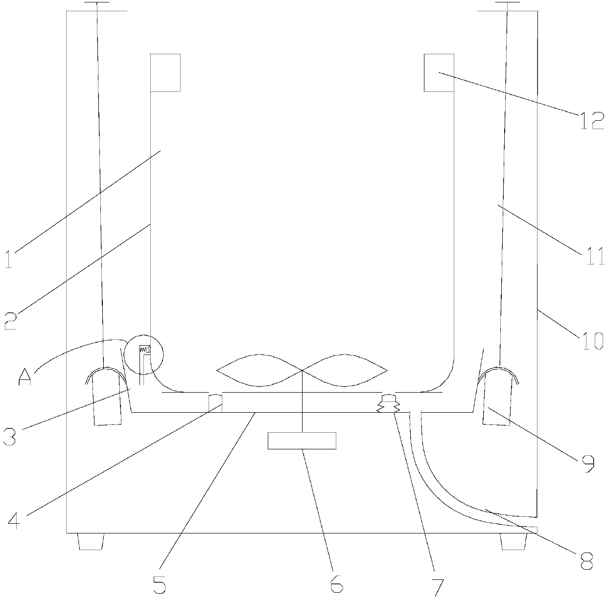
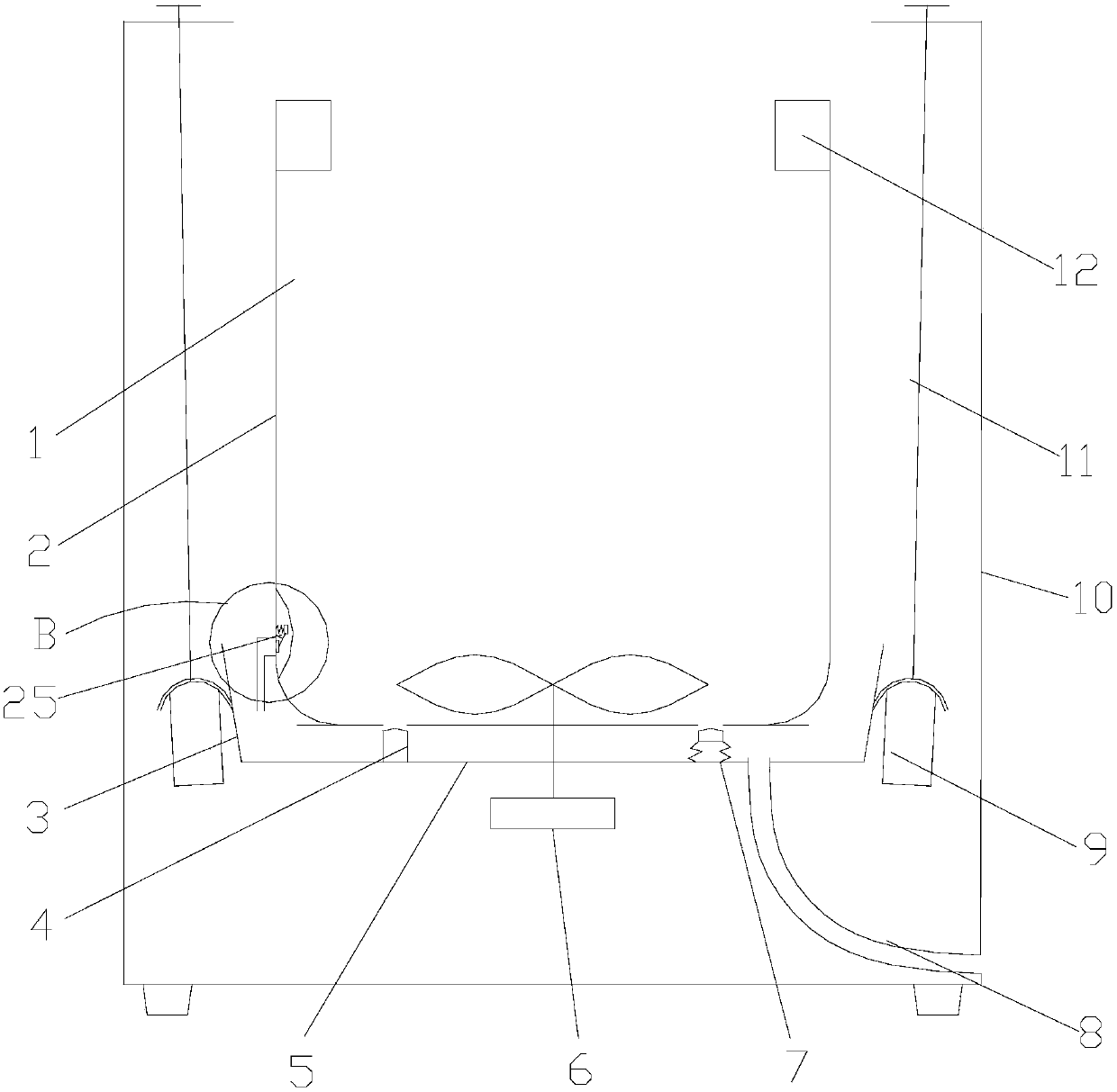
[0032] Such as Figure 1 to Figure 2 As shown, a washing machine is introduced in this embodiment, which includes a casing 10, a washing bucket 2 arranged in the casing 10, and a motor 6 for driving the washing bucket 2 to rotate. The water channel 1 leading to the upper part and the balance ring 12 for maintaining the dynamic balance of the washing machine. In the embodiment of the present invention, the washing bucket 2 is a non-porous inner bucket, and the inner bucket is a closed container after the cover of the washing machine is closed. It integrates the dual functions of holding washing water and being electrically driven to rotate, and washing clothes with washing water, so that The washing machine does not need to be equipped with an outer tub, and only needs to utilize the washing tub 2 to achieve the effect of washing clothes at the same time.

[0033] In this embodiment, the washing machine also includes a bottom mounting plate 5 and a suspension rod 11 of the sho...

Embodiment 2

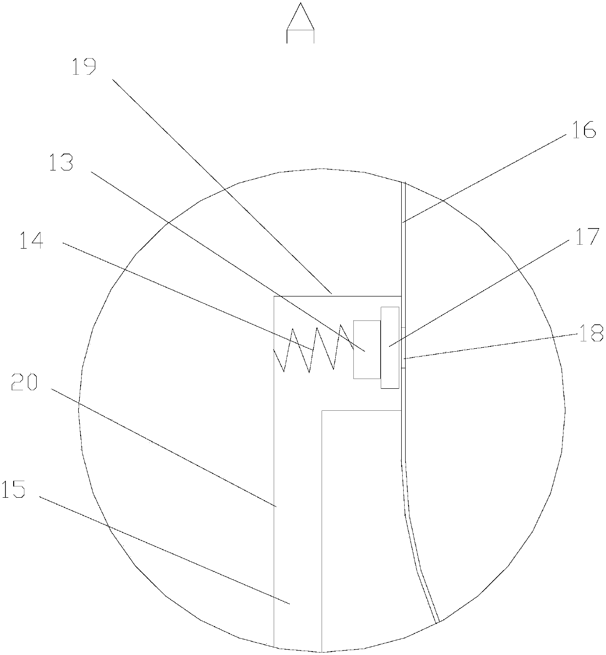
[0042] Such as figure 2 As shown, a centrifugal valve is introduced in this embodiment. The centrifugal valve includes an elastic seal 17, a counterweight 13, a spring 14 and a fixing member. The elastic seal 17 is correspondingly blocked in the opening 18 from the outside to the inside. At the position, the outer end of the elastic sealing member 17 is connected with the fixing member via the spring 14, and the fixing member is fixedly connected with the wall 16 of the washing tub, and the elastic sealing member 17 is equipped with a counterweight 13.

[0043] In this embodiment, the fixing part is the water outlet pipeline 15, the water outlet pipeline 15 includes a horizontal extension section 19 and a vertical extension section 20, the left end of the horizontal extension section 19 communicates with the opening 18, and the right end communicates with the vertical extension section 20. The upper end is connected, and the lower end of the vertical extension section 20 is c...

Embodiment 3

[0049] In this embodiment, the wall of the washing tub 2 gradually increases in diameter from the upper and lower ends to the direction of the opening 18, and the opening 18 is located on the horizontal cross-section of the largest diameter of the washing tub 2. During the high-speed spin dehydration process of the washing machine, the washing tub 2. Under the action of centrifugal force, the internal water flow converges and flows toward the opening 18, which facilitates the discharge of washing water and improves the efficiency of dehydration of clothes.

[0050] preferred, such as figure 1 As shown, the wall of the washing bucket 2 is a tapered bucket whose diameter gradually increases from top to bottom, and the opening 18 is arranged at the lowest part of the wall of the washing bucket 2, so that the washing water in the washing bucket 2 is blown by centrifugal force. When converging and flowing to the opening, gravity provides flow power to the washing water, assisting t...


PUM


Abstract

The invention discloses a washing machine. The washing machine comprises a washtub and a centrifugal valve, wherein the washtub is a closed inner tub with an open hole for draining washing water, thecentrifugal valve is installed at the inner wall face in the open hole in the washtub, in the normal washing process of the washing machine, the centrifugal valve blocks the open hole from the inner side to the outer side of the washtub, and the open hole is formed under the effect of centrifugal force of the centrifugal valve when the washtub of the washing machine rotates at high speed. The washtub is the inner tub with no hole, the open hole for draining washing water is formed in the tub, due to the centrifugal valve arranged outside the open hole, it can be ensured that the tub does not leak water in the washing process, and the dehydration and drainage functions under the high-speed rotation can be achieved. In addition, due to an annular water blocking structure arranged at a bottominstalling plate, an outward inclination structure is adopted preferentially, friction generated at the lower portion of the washtub and the water blocking structure can be avoided, and the water containing capability of the lower portion can be improved.

Description

technical field [0001] The invention belongs to the technical field of laundry devices, and in particular relates to a washing machine equipped with a non-porous inner tub. Background technique [0002] The washing machine in the prior art generally includes a washing tub and an outer tub, the outer tub is equipped with a washing tub, the outer tub is used to accommodate washing water, and clothes are placed in the washing tub; washing structures such as pulsators are installed inside the washing tub, and the washing tub and / or Or the pulsator rotates under the drive of the motor to generate washing water flow to wash the clothes. In the washing process, the washing bucket is connected with the outer tub through the dehydration hole provided on it, so that the inside of the washing bucket and the outer tub are filled with water, so there are three problems in the conventional washing machine in the prior art: first, waste Water, in the actual work, only the water in the was...

Claims


Application Information

Patent Timeline
Patent Type & Authority Applications(China)
IPC IPC(8): D06F37/12D06F23/04D06F39/08D06F37/42
CPCY02B40/00
Inventor 郝兴慧劳春峰许升吕艳芬吴迪
Owner QINGDAO HAIER WASHING MASCH CO LTD
Learn More