
Full-automatic three-roller brake machine core
A three-roller gate, fully automatic technology, applied in the direction of power control mechanism, wing leaf control mechanism, door/window accessories, etc., can solve the problems of poor state switching effect, injury, damaged personnel and other problems, and achieve excellent operation effect , good safety, the effect of achieving anti-collision function
- Summary
- Abstract
- Description
- Claims
- Application Information
AI Technical Summary
Problems solved by technology
Method used
Image

Examples
Embodiment 1
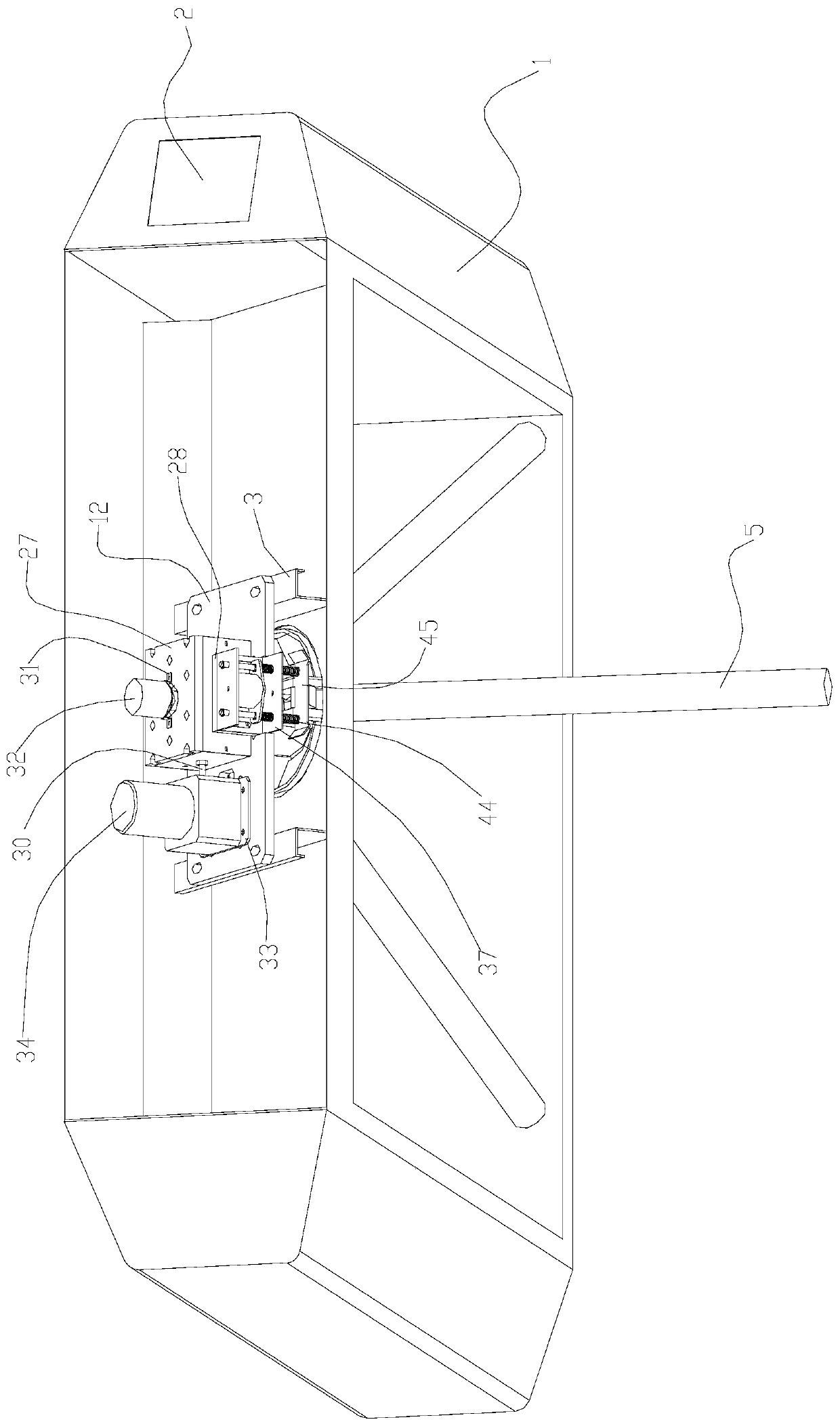
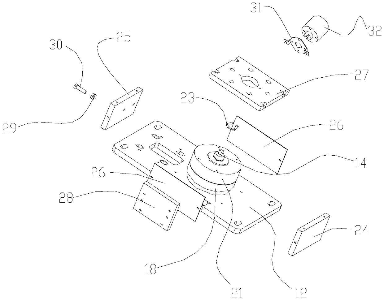
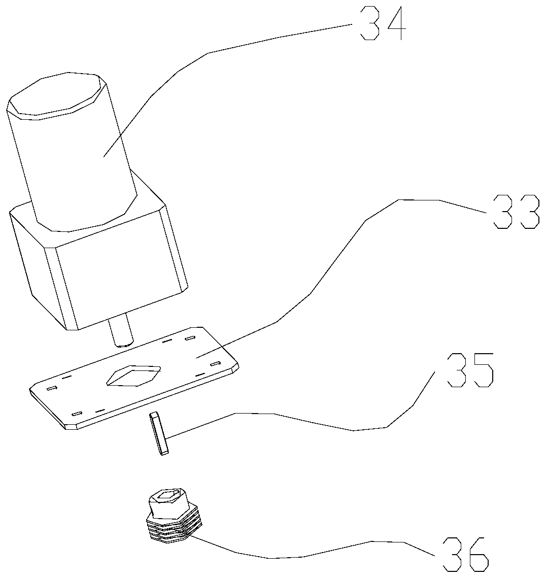
[0026] see Figure 1-8 , in an embodiment of the present invention, a fully automatic three-roller gate mechanism includes a vertically arranged box body 1, the upper right end of the box body 1 is inlaid with a card swiping window 2, and the middle position of the inner upper half of the box body 1 is horizontal An installation base plate 12 is provided, and base plate brackets 3 are arranged symmetrically on the lower side of the installation base plate 12. A motor fixing plate 33 is arranged horizontally, the upper end of the motor fixing plate 33 is provided with a driving motor 34, the lower end of the driving motor 34 is provided with a motor belt bearing sleeve 36 through a key 35, and a main shaft 14 is provided through the middle position of the upper end of the installation base plate 12, and the installation base plate The main shaft 14 on the upper side of 12 is provided with a driven plate 16, a friction plate 18 and a pressure plate 21 in sequence, and the driven...
Embodiment 2
[0029] On the basis of the first embodiment, through the cooperation of the No. 1 spring 42 and the No. 2 spring 44, the double spring reset is realized, so that the state switching of the push plate 45 is accurate, and the stable operation of the equipment is guaranteed.
PUM
 Abstract
Description
Claims
Application Information