Light source capable of generating circularly polarized light through utilization of electricity

A technology of circularly polarized light and light source, applied in polarizing components, circuits, electrical components, etc., to save time and facilitate time

Inactive Publication Date: 2019-06-11
金华伏安光电科技有限公司
View PDF5 Cites 2 Cited by
  • Summary
  • Abstract
  • Description
  • Claims
  • Application Information

AI Technical Summary

Problems solved by technology

[0007] In the prior art, there is no light source that directly electro-generates circularly polarized light. If a light source that directly electro-generates circularly polarized light can be designed, there is no need to adjust the compensator frequently to generate circularly polarized light, which can greatly improve the Improve the efficiency of this optical experiment and promote the application of circularly polarized light

Method used


Image

  • Light source capable of generating circularly polarized light through utilization of electricity
  • Light source capable of generating circularly polarized light through utilization of electricity

Examples


Embodiment 1

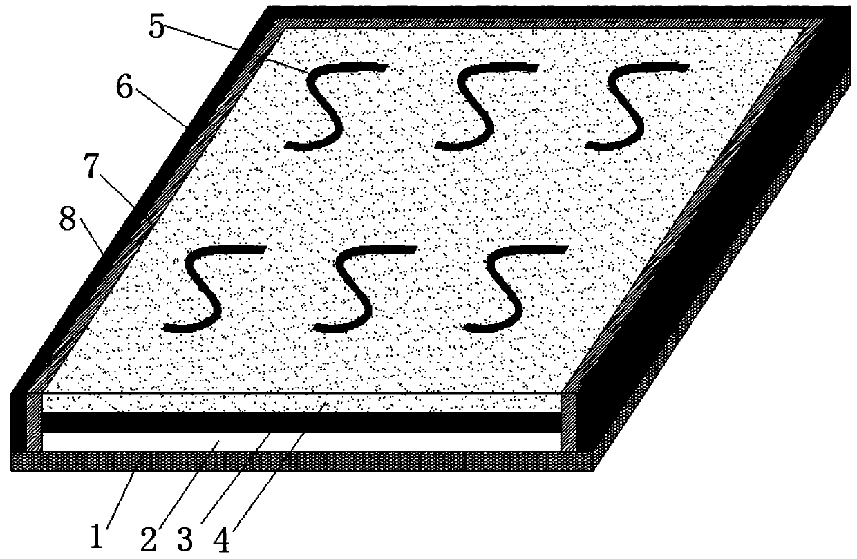
[0026] This embodiment provides a figure 1 The light source for electrogenerating circularly polarized light shown includes a substrate layer 1 that mainly plays a supporting role, and a first metal layer 2 as a negative electrode of a power supply is arranged above the substrate layer 1, and a metal layer 2 is arranged above the first metal layer 2. The quantum well layer 3, the function of the quantum well layer 3 is mainly to emit light under the condition of being energized; the second metal layer 4 is arranged above the quantum well layer 3, and the second metal layer 4 is used as the positive electrode of the power supply. The second metal layer 4 is provided with an array composed of a plurality of chiral metal holes; the array of chiral metal holes can convert the linearly polarized light generated by the quantum well layer 3 into circularly polarized light, and the array composed of different chiral metal holes , for different linearly polarized light, the effective r...

Embodiment 2

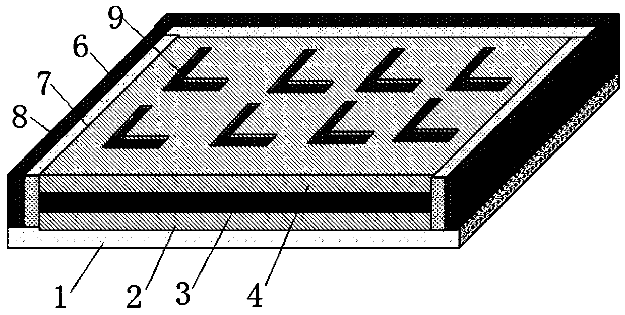
[0036] This embodiment provides a figure 2 The illustrated light source for electrogenerating circularly polarized light includes a substrate layer 1 that mainly plays a supporting role, and a first metal layer 2 as a negative electrode of a power supply is arranged above the substrate layer 1, and a first metal layer 2 is arranged above the first metal layer 2. There is a quantum well layer 3, and the function of the quantum well layer 3 is mainly to emit light under the condition of being energized; a second metal layer 4 is arranged above the quantum well layer 3, and the second metal layer 4 is used as a positive electrode of a power supply, and The second metal layer 4 can increase the quantum efficiency of the quantum well layer 3. Specifically, when the second metal layer 4 is loaded with different voltages, the internal carrier concentration is different. The higher the carrier concentration, the better the quantum well layer. 3, the higher the efficiency of light wav...


PUM

PropertyMeasurementUnit
Lengthaaaaaaaaaa
Widthaaaaaaaaaa
Thicknessaaaaaaaaaa

Abstract

The invention relates to a light source capable of generating circularly polarized light through utilization of electricity. The light source comprises a substrate layer, wherein a first metal layer is set on the substrate layer; a quantum well layer is set on the first metal layer; a second metal layer is set on the quantum well layer; and an array composed of a plurality of chiral metal holes isset on the second metal layer. According to the light source capable of generating circularly polarized light through utilization of electricity, the circularly polarized light can be directly generated; through utilization of the chiral metal holes, a phase of the linearly polarized light is deviated and after the light is superposed, the circularly polarized light is formed; the circularly polarized light does not need to be generated through utilization of a biaxial crystal; and the generated circularly polarized light can be adjusted through adjustment of a voltage loaded to the quantum well layer. The light source is convenient. Time is reduced.

Description

technical field [0001] The invention belongs to the technical field of circularly polarized light sources, and in particular relates to a light source for electrogenerating circularly polarized light. Background technique [0002] Circularly polarized light is a special case of elliptically polarized light, which is produced by rotating the endpoint of the electric vector to trace a circular trajectory. When the propagation directions are the same, the vibration directions are perpendicular to each other and the phase difference is constant as After the two plane polarized lights of π are superimposed, the circularly polarized light whose electric vector changes regularly can be synthesized. [0003] In the prior art, the relatively common methods for generating circularly polarized light are through Babinet compensators and Sorey compensators. [0004] The Babinet compensator is a composite prism composed of two quartz wedge-shaped plates whose optical axes are perpendic...

Claims


Application Information

Patent Timeline
IPC IPC(8): G02B5/30H01L33/06
Inventor 不公告发明人
Owner 金华伏安光电科技有限公司
Why Eureka
Try Eureka