
Backlight module and display device

A backlight module and backplane technology, applied in the direction of identification devices, instruments, etc., can solve the problems of optical film deformation, film scratches, shadows, etc., achieve high light transmittance and avoid deformation effects

Inactive Publication Date: 2019-06-11
WUHAN CHINA STAR OPTOELECTRONICS TECH CO LTD
View PDF8 Cites 0 Cited by
  • Summary
  • Abstract
  • Description
  • Claims
  • Application Information

AI Technical Summary

Problems solved by technology

[0003] According to the principle of heat transfer, the heat in the existing backlight module will radiate to the surroundings and conduct to the reflector or optical film through the light guide plate. In order to solve the heat dissipation problem, graphite is usually added behind the backplane or reflector film, but the heat will still cause the deformation of the optical film during diffusion and conduction, causing scratches and shadows on the film

Method used


Image

  • Backlight module and display device
  • Backlight module and display device
  • Backlight module and display device

Examples


Embodiment Construction

[0032] The preferred embodiments of the present invention will be described in detail below with reference to the accompanying drawings, so as to fully introduce the technical content of the present invention to those skilled in the art, to exemplify the implementation of the present invention, to make the technical content disclosed in the present invention clearer, and to make the present invention clearer. Those skilled in the art will more readily understand how to implement the present invention. However, the present invention can be embodied in many different forms of embodiments, the protection scope of the present invention is not limited to the embodiments mentioned herein, and the description of the following embodiments is not intended to limit the scope of the present invention.

[0033] The following embodiments are described with reference to the accompanying drawings to illustrate specific embodiments in which the invention may be practiced. The directional term...


PUM


Abstract

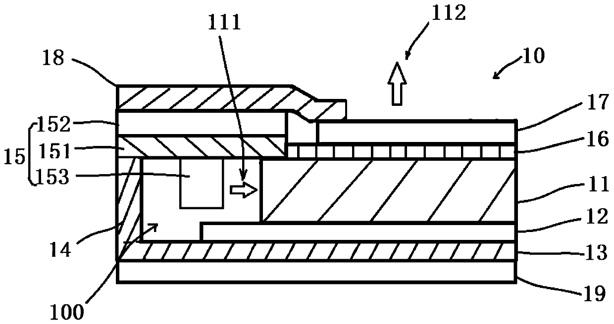
The invention discloses a backlight module and a display device. The backlight module comprises a light guide plate, an optical diaphragm and a heat insulation diaphragm, wherein the heat insulation diaphragm is arranged between the light guide plate and the optical diaphragm. The backlight module and the display device have the advantages that the heat insulation diaphragm can block the transferof heat to the optical diaphragm, so that the heat can only be transferred to the side where a reflector plate is located, the reflector plate transfers the heat to a back plate, and then a heat dissipation device emits the heat into the external environment, thereby effectively protecting the optical diaphragm, and avoiding the situation that the diaphragms are scratched and the light emitting effect is affected, for example, the umbra is generated due to the deformation of the optical diaphragm caused by the heat absorption.

Description

technical field [0001] The invention relates to the fields of displays and the like, in particular to a backlight module and a display device. Background technique [0002] Heat has always been the main reason for the deformation of the optical film in the backlight module. At present, most display modules use heat dissipation to improve the deformation of the optical film in the backlight module. Although this method is effective, the heat Still affects the optical film, causing it to deform. Therefore, it is necessary to prevent the heat from being transmitted through the optical film in order to effectively suppress the deformation of the optical film and solve a series of problems caused by the deformation of the optical film. [0003] According to the principle of heat transfer, the heat in the existing backlight module will be dissipated around, and will be conducted to the reflective sheet or the optical film through the light guide plate. In order to solve the probl...

Claims


Application Information

Patent Timeline
Patent Type & Authority Applications(China)
IPC IPC(8): G09F9/00
Inventor 左小艳
Owner WUHAN CHINA STAR OPTOELECTRONICS TECH CO LTD
Learn More