Minimally invasive incision and tension reduction device for compartment syndrome

A syndrome and fascia technique, applied in the mechanical field, can solve problems such as deep fasciotomy that is difficult to control and easy to damage blood vessels, nerves, muscle soft tissues, etc.

Active Publication Date: 2020-12-08
NANJING FIRST HOSPITAL
View PDF8 Cites 0 Cited by
  • Summary
  • Abstract
  • Description
  • Claims
  • Application Information

AI Technical Summary

Problems solved by technology

[0004] The object of the present invention is to provide a minimally invasive incision and tension reduction instrument for compartment syndrome, to solve the problem in the above-mentioned background technology that it is difficult to control the deep fascia incision, and it is easy to damage blood vessels, nerves, Muscle and other soft tissue problems

Method used


Image

  • Minimally invasive incision and tension reduction device for compartment syndrome
  • Minimally invasive incision and tension reduction device for compartment syndrome
  • Minimally invasive incision and tension reduction device for compartment syndrome

Examples


Embodiment 1

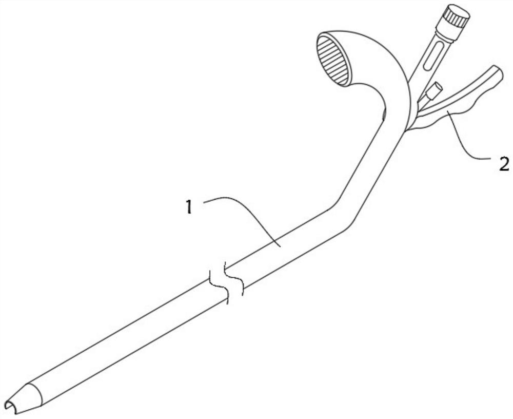
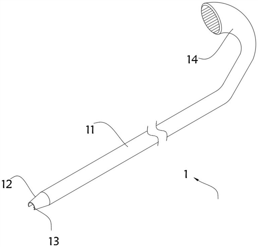
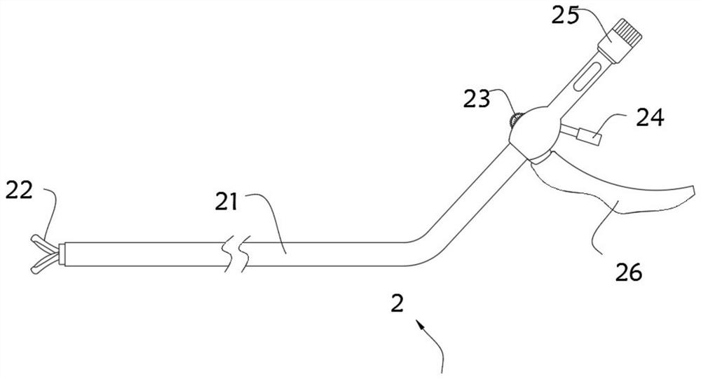
[0046] On the one hand, the present invention provides minimally invasive incision and tension reduction instruments for compartment syndrome, such as Figure 1-Figure 6 As shown, it includes an outer tube body 1 and an operating tube body 2 installed inside the outer tube body 1, the outer tube body 1 includes a sleeve 11, one end of the sleeve 11 is equipped with a chuck 12, and the other end of the sleeve 11 is provided with a handle The holding head 14, the bottom of the casing 11 and the clamping head 12 are all provided with strip grooves 13, the operating pipe body 2 includes an inner pipe 21, one end of the inner pipe 21 is provided with a heading scissors 22, and the inner pipe 21 is provided with a The adjusting tooth 23 of the opening angle of the heading scissors 22 and the safety lever 24 for fixing the opening angle of the heading scissors 22, a knife seat 27 is installed on one end of the heading scissors 22, and the heading scissors 22 includes a pair of knife r...

Embodiment 2

[0054] As the second embodiment of the present invention, in order to facilitate the adjustment of the opening angle of the heading scissors 22, the inventors improved the adjustment tooth 23, as a preferred embodiment, such as Figure 7-Figure 9 As shown, a transmission tooth 231 is installed on the side of the inner tube 21 close to the adjustment tooth 23, the outer wall of the adjustment tooth 23 is provided with an angle dial 232, the outer wall of the transmission tooth 231 is equipped with a rotating shaft 233, and the outer wall of the rotating shaft 233 is covered with Clockwork spring 234, the outer wall of the rotating shaft 233 is annularly wound with a first pulling rope 235, one end of the bumper 24 is equipped with a clamping plate 241, a plurality of clamping teeth 242 are installed on the clamping plate 241, the adjusting gear 23 and the transmission gear 231 engage.

[0055] In this embodiment, the outer wall of the inner tube 21 is provided with a notch for ...

Embodiment 3

[0061] As a third embodiment of the present invention, in order to facilitate the adjustment of the extension length of the heading scissors 22, the inventors improved the adjustment head 25, as a preferred embodiment, such as Figures 11 to 12 As shown, the inner tube 21 is also provided with an adjusting head 25 for adjusting the extension length of the heading scissors 22, a transmission shaft 251 is installed on one end of the adjusting head 25, and a ball screw nut 252 is installed on the side wall of the knife seat 27. The ball screw nut 252 is provided with a ball screw 253, and a connector 254 is installed between the ball screw 253 and the transmission shaft 251. The connector 254 includes a mounting seat 255, and rotating shafts 256 are respectively installed on both sides of the outer wall of the mounting seat 255. A pair of baffle plates 257 are arranged in the seat 255, and a mounting plate 258 is arranged between the two baffle plates 257. The inner wall of the ba...


PUM


Abstract

The invention relates to the technical field of machinery, in particular to a minimally invasive incision decompression device for osteofascial compartment syndrome, especially a device for deep fascia minimally invasive incision decompression of a patient with the osteofascial compartment syndrome. The device includes an external tube body and an operation tube body installed in the external tubebody. The minimally invasive incision decompression device drives a transmission tooth to rotate through an adjusting tooth to wind a first pulling rope onto a rotating shaft, so that the two ends ofa connecting strip are fitted to the intermediate position, and two shanks are driven to be attached to the intermediate position to achieve angle adjustment of upset head scissors. A clamping toothof a safety lever is clamped on the transmission tooth, so that the opening angle of the upset head scissors is fixed, and the upset head scissors are prevented from being closed during operation. Anadjusting head is rotated to drive a transmission shaft to rotate, and the position of a holder can be changed by changing the position of a ball screw nut, so that adjustment of the extension lengthof the upset head scissors can be achieved.

Description

technical field [0001] The invention relates to the field of mechanical technology, in particular to a minimally invasive incision and tension reduction instrument for compartment syndrome. Background technique [0002] Compartment syndrome is a series of early symptoms and signs of muscles and nerves in the compartment formed by bone, interosseous membrane, intermuscular septum and deep fascia due to acute ischemia and hypoxia. Also known as acute compartment syndrome and compartment syndrome. Once compartment syndrome is diagnosed, the deep fascia should be incised and decompressed immediately. Early and complete deep fascia decompression is the only effective way to prevent muscle and nerve avascular necrosis. [0003] The existing osteofascial compartment syndrome requires multiple open incisions to reduce tension, the skin incision is large, the trauma is large, and the wound surface oozes blood and oozes a lot. There are no special tools for minimally invasive incis...

Claims


Application Information

Patent Timeline
Patent Type & Authority Patents(China)
IPC IPC(8): A61B17/3201
Inventor 杨大伟
Owner NANJING FIRST HOSPITAL
Why Eureka
Try Eureka