Clamp mounting piece

A technology of mounting parts and clips, which is applied in the direction of workpiece clamping devices, manufacturing tools, etc., can solve the problem of difficult contact between clips and clamped objects, and achieve the effect of fast and convenient assembly and disassembly

Pending Publication Date: 2019-06-14
GUANGDONG UNIV OF TECH
View PDF1 Cites 2 Cited by
  • Summary
  • Abstract
  • Description
  • Claims
  • Application Information

AI Technical Summary

Problems solved by technology

[0002] At present, there are many kinds of grippers on the market. The driving methods of the clips include parallelogram, rack and pinion drive, etc. There is a small gripping module driven by a steering gear (patent number: CN201721204234.3), and the clip is made of The steering gear is directly driven...

Method used


Image

  • Clamp mounting piece
  • Clamp mounting piece
  • Clamp mounting piece

Examples


Embodiment 1

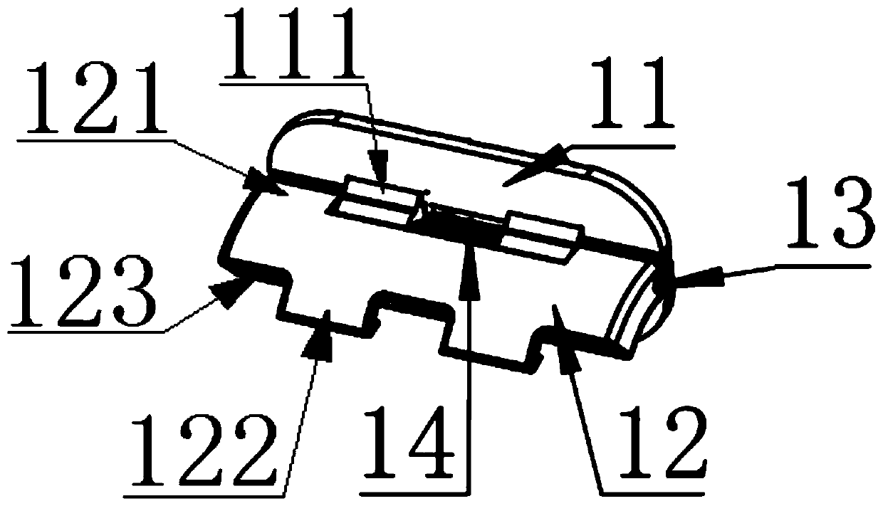
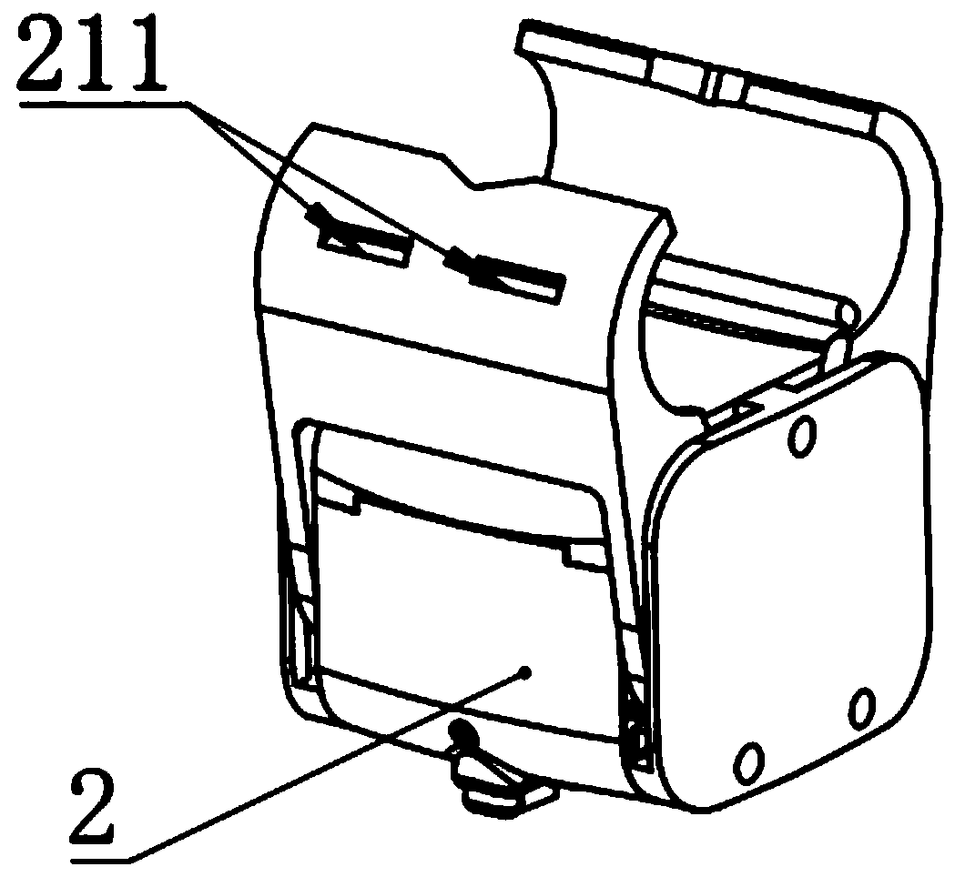
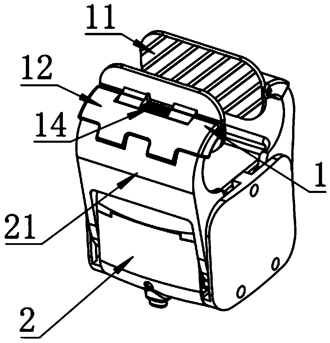
[0023] Such as figure 1 — Figure 4 As shown, the clip mounting part provided by this specific embodiment mainly includes: a clamping plate 11 , a metal shaft 13 , a mounting sleeve 12 , and a torsion spring 14 . Wherein, the surface of the clamping surface of the clamping plate 11 has slanted lines. In order to increase the friction of the clamping surface, two first protrusions 111 with through holes protrude from the back perpendicular to the clamping surface, and the through holes are provided for the metal shaft. 13; the side of the mounting sleeve 12 close to the clamping plate 11 has two protruding second protrusions 121 with through holes, the through holes are also for the metal shaft 12 to be loaded, and the two sides of the clamping plate 11 A first bump 111 is located between the two second bumps 121 of the installation sleeve 12, and the metal shaft 13 passes through the through holes of the first bump 111 and the second bump 121 to clamp the plate 11 and the ins...


PUM


Abstract

The invention relates to the technical field of clamping devices, in particular to a clamp mounting piece adapted to a small clamping module automatically. The clamp mounting piece is used for the small clamping module, and comprises a clamping plate, a metal shaft, a mounting sleeve and a torsion spring, the clamping plate is rotationally connected with the mounting sleeve through the metal shaft, the torsion spring is arranged on the metal shaft and is used for resetting the clamping plate in a non-clamping state, and the mounting sleeve is arranged on a clamp of the small clamping module. The clamp mounting piece can be quickly and conveniently arranged on the clamp of the small clamping module, moreover, the clamping plate can rotate, the posture of the clamping plate can be automatically adjusted according to the shapes of clamped parts with different shapes, a better clamping effect can be achieved, and the problem at the present stage in the field is solved.

Description

technical field [0001] The invention relates to the technical field of clamps, and more specifically, relates to a clamp mounting part of an adaptive small clamping module. Background technique [0002] At present, there are many kinds of grippers on the market. The driving methods of the clips include parallelogram, rack and pinion drive, etc. There is a small gripping module driven by a steering gear (patent number: CN201721204234.3), and the clip is made of The steering gear is directly driven, and the clip rotates around the output shaft of the steering gear to complete the opening and closing of the clip. Due to the movement mode of the clip, the clip can only complete the clamping of the rod. It is difficult to realize the surface contact between the clamp and the object to be clamped by the movement mode. In order to allow the clamp of this type of structure to clamp objects other than the rod while maintaining the original function of clamping the rod, and improve t...

Claims


Application Information

Patent Timeline
IPC IPC(8): B25B11/00
Inventor 叶文驹管贻生冯世豪陈翔杨宇峰朱焱行蔡传武
Owner GUANGDONG UNIV OF TECH
Why Eureka
Try Eureka