
Working couplet, multi-way valve and excavator

A technology of working coupling and working oil port, applied in the direction of earth mover/shovel, construction, etc., can solve the problems of increasing manufacturing cost, increasing the volume of the main valve, increasing the difficulty of processing, etc., achieving constant pressure difference and simplifying the valve. body structure, the effect of precise control of flow

Active Publication Date: 2021-09-03
JIANGSU XCMG CONSTR MASCH RES INST LTD
View PDF5 Cites 0 Cited by
  • Summary
  • Abstract
  • Description
  • Claims
  • Application Information

AI Technical Summary

Problems solved by technology

[0006] 1) The addition of more confluence working unions will cause the structure of the main valve to be complicated and increase the difficulty of processing, especially the load-sensitive multi-way valve;
[0007] 2) Adding more combined working unions will increase the volume of the main valve and increase the manufacturing cost;
[0008] 3) In the throttling system, the bucket can only achieve single-action confluence, which will limit the excavation speed of the bucket and reduce the operating efficiency of the excavator;
[0009] 4) In the load-sensing system, the bucket realizes the confluence outside the valve by adding a confluence valve block, which makes the structure of the main valve complex and increases the difficulty of the logic control of the main valve;
[0010] 5) In the load sensing system, the bucket cannot achieve confluence in the valve, which limits the adaptability of the main valve to certain working conditions and increases the difficulty of debugging

Method used


Image

  • Working couplet, multi-way valve and excavator
  • Working couplet, multi-way valve and excavator
  • Working couplet, multi-way valve and excavator

Examples


Embodiment Construction

[0080] The technical solutions in the embodiments of the present invention will be clearly and completely described below in conjunction with the drawings in the embodiments of the present invention. Apparently, the described embodiments are only some of the embodiments of the present invention, not all of them. Based on the embodiments of the present invention, all other embodiments obtained by persons of ordinary skill in the art without creative efforts fall within the protection scope of the present invention.

[0081] In describing the present invention, it is to be understood that the terms "central", "longitudinal", "transverse", "front", "rear", "left", "right", "vertical", "horizontal", The orientations or positional relationships indicated by "top", "bottom", "inner", "outer", etc. are based on the orientations or positional relationships shown in the drawings, and are only for the convenience of describing the present invention and simplifying the description, rathe...


PUM


Abstract

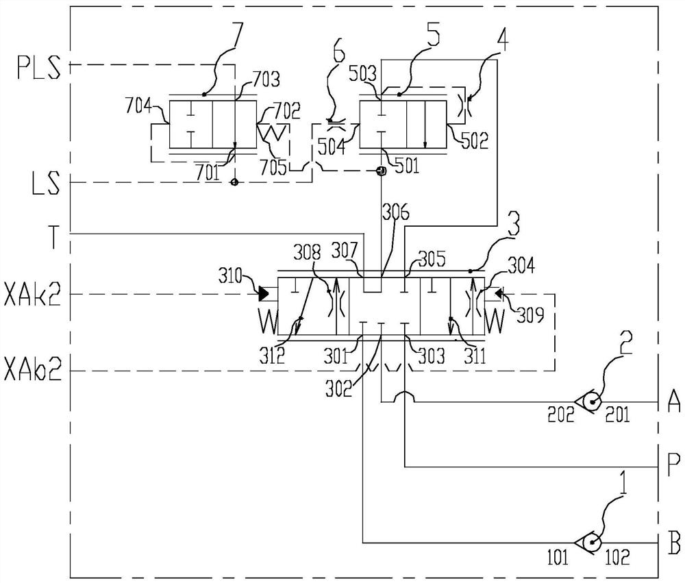
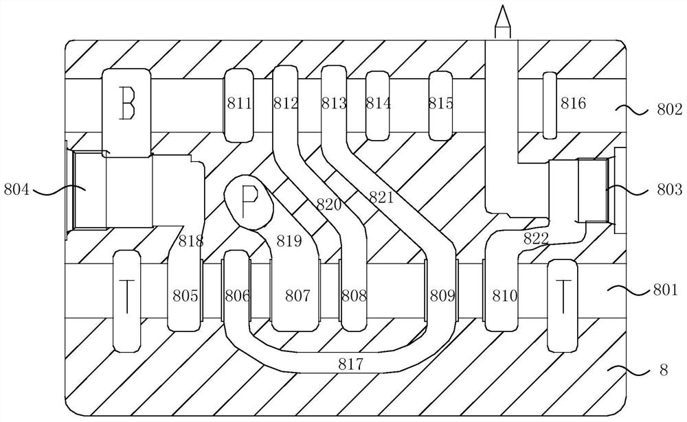
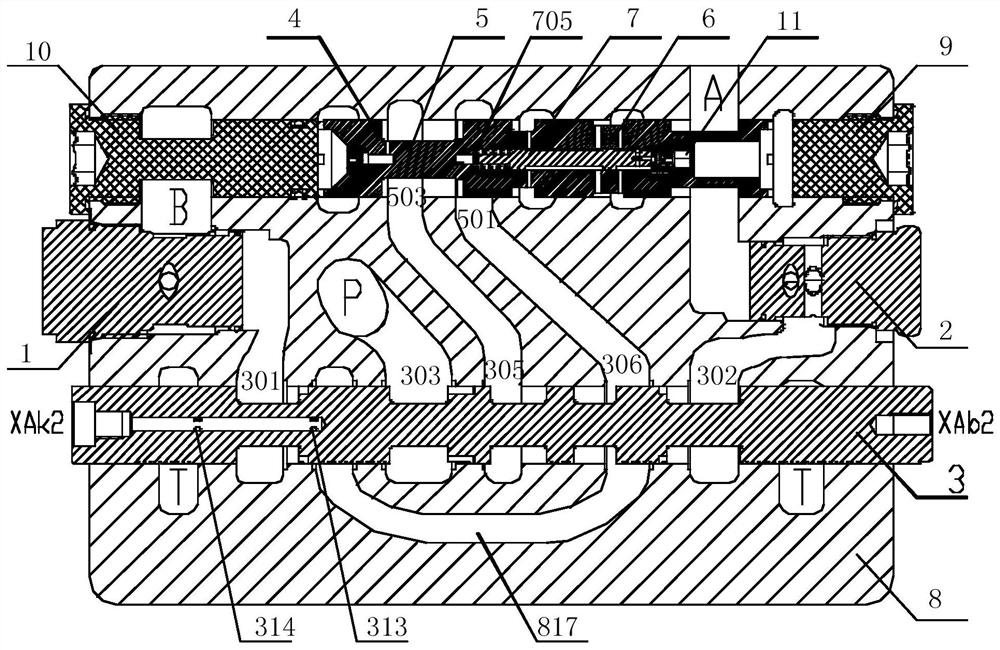
The invention relates to a working coupler, a multi-way valve and an excavator. Wherein, the working coupling includes: a reversing valve, which can switchably lead the hydraulic oil to the first actuator oil inlet and the second actuator oil inlet of the working coupling; a pressure compensation valve, whose working oil port is connected to the reversing valve The working oil port is connected to dynamically adjust the pressure of the hydraulic oil flowing to the reversing valve according to the load. The hydraulic oil flowing out of the pressure compensation valve flows through the reversing valve to the oil inlet of the first actuator or the oil inlet of the second actuator ; and a booster valve, the first working oil port of which is connected to the load feedback oil supply port of the working connection, and the second working oil port is connected to the load feedback oil port of the working connection and the control oil port of the pressure compensation valve. It is used to dynamically adjust the pressure of hydraulic oil flowing to the control port of the pressure compensation valve according to the load. The invention simplifies the structure of the valve body; by dynamically adjusting and compensating the load pressure, the pressure difference of the reversing valve is constant, and the precise control of the flow is realized.

Description

technical field [0001] The invention relates to the field of engineering machinery, in particular to a working coupler, a multi-way valve and an excavator. Background technique [0002] For medium and large hydraulic excavators with a tonnage of 21 tons and above, the dual-pump dual-circuit hydraulic multi-way main valve with dual-pump oil supply is mostly used. The purpose is to better realize the speed control of the actuator and improve the operation of the excavator. efficiency and lower fuel consumption. For example, when the boom is raised, the stick is retracted and swung outward, and the bucket is retracted, it is necessary to supply oil with two pumps, while when the boom is lowered and the bucket is swung outward, it is necessary to supply oil with a single pump. It can meet the flow demand of the actuator. [0003] The mainstream system of medium-tonnage excavators is the throttling system. The throttling system can well adapt to the complex load conditions of ...

Claims


Application Information

Patent Timeline
Patent Type & Authority Patents(China)
IPC IPC(8): E02F9/22
Inventor 景军清夏书强杨涛
Owner JIANGSU XCMG CONSTR MASCH RES INST LTD
Learn More