Central force balanced drainage valve lifting mechanism

A technology of lifting mechanism and drain valve, which is applied to water supply devices, flushing equipment with water tanks, buildings, etc., which can solve problems such as increased friction, increased lateral friction, and button lifting jamming, etc., to achieve extended use Life, reduce friction, reduce the effect of key pressure

Pending Publication Date: 2019-06-14
广东安百利卫浴科技有限公司
View PDF11 Cites 2 Cited by
  • Summary
  • Abstract
  • Description
  • Claims
  • Application Information

AI Technical Summary

Problems solved by technology

[0002] In the drain valve of the toilet tank, the pressing rod and the lifting rod of the button are located near the central axis of the drain valve. In order to turn the downward force of the button into an upward pulling force, a lever is arranged under the button, and a cross bar is arranged on the top of the lifting rod. The movable connection of the crossbar plays the role of pulling up the lifting rod, which makes room in space, but increases the lateral friction force, causing the button to be pulled and jammed, and the friction force increases after long-term use, which is easy to be stuck die

Method used


Image

  • Central force balanced drainage valve lifting mechanism
  • Central force balanced drainage valve lifting mechanism
  • Central force balanced drainage valve lifting mechanism

Examples


Embodiment Construction

[0027] In order to make the technical problems, technical solutions and beneficial effects to be solved by the present invention clearer and clearer, the present invention will be further described in detail below in conjunction with the accompanying drawings and embodiments. It should be understood that the specific embodiments described here are only used to explain the present invention, not to limit the present invention.

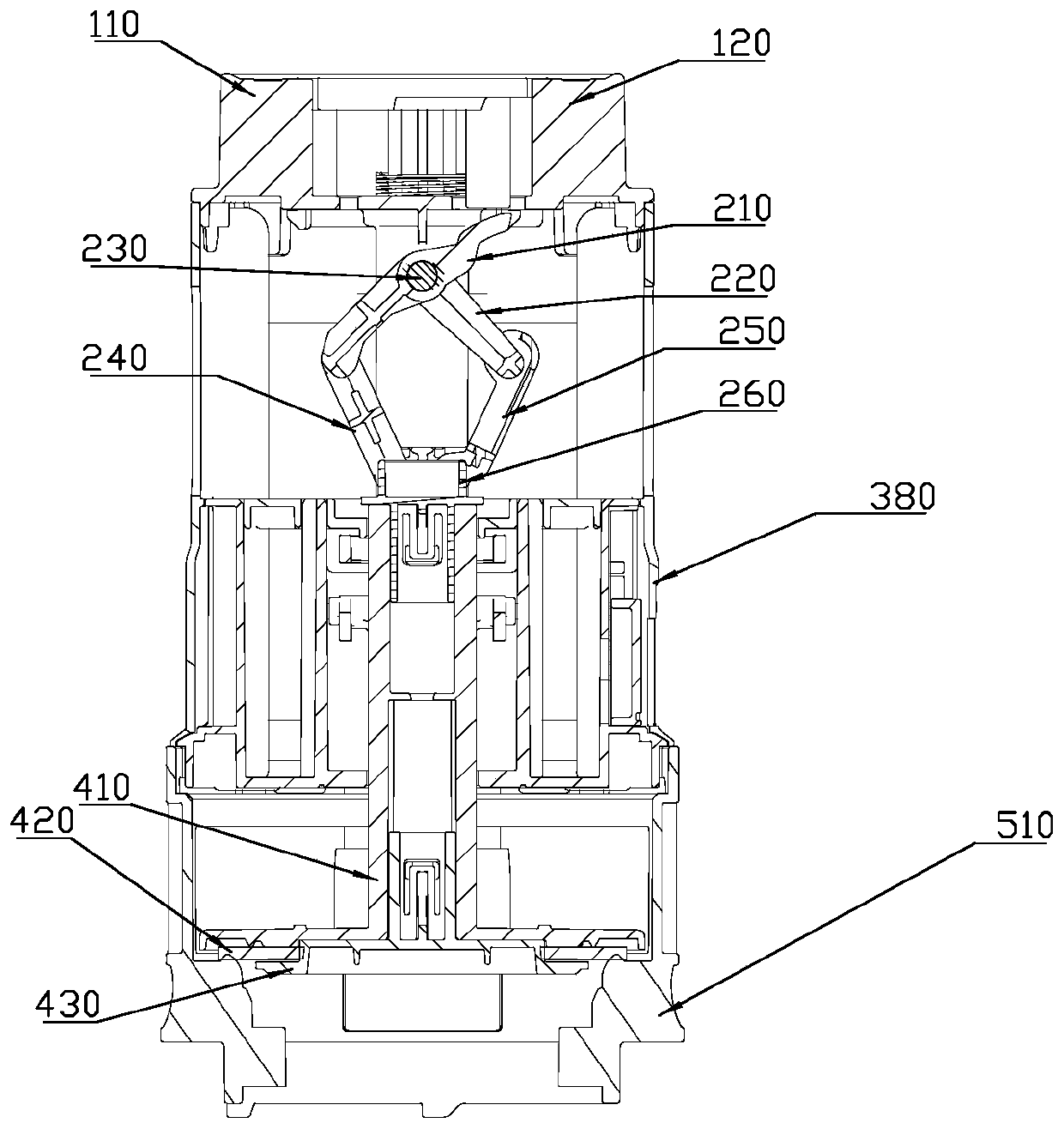
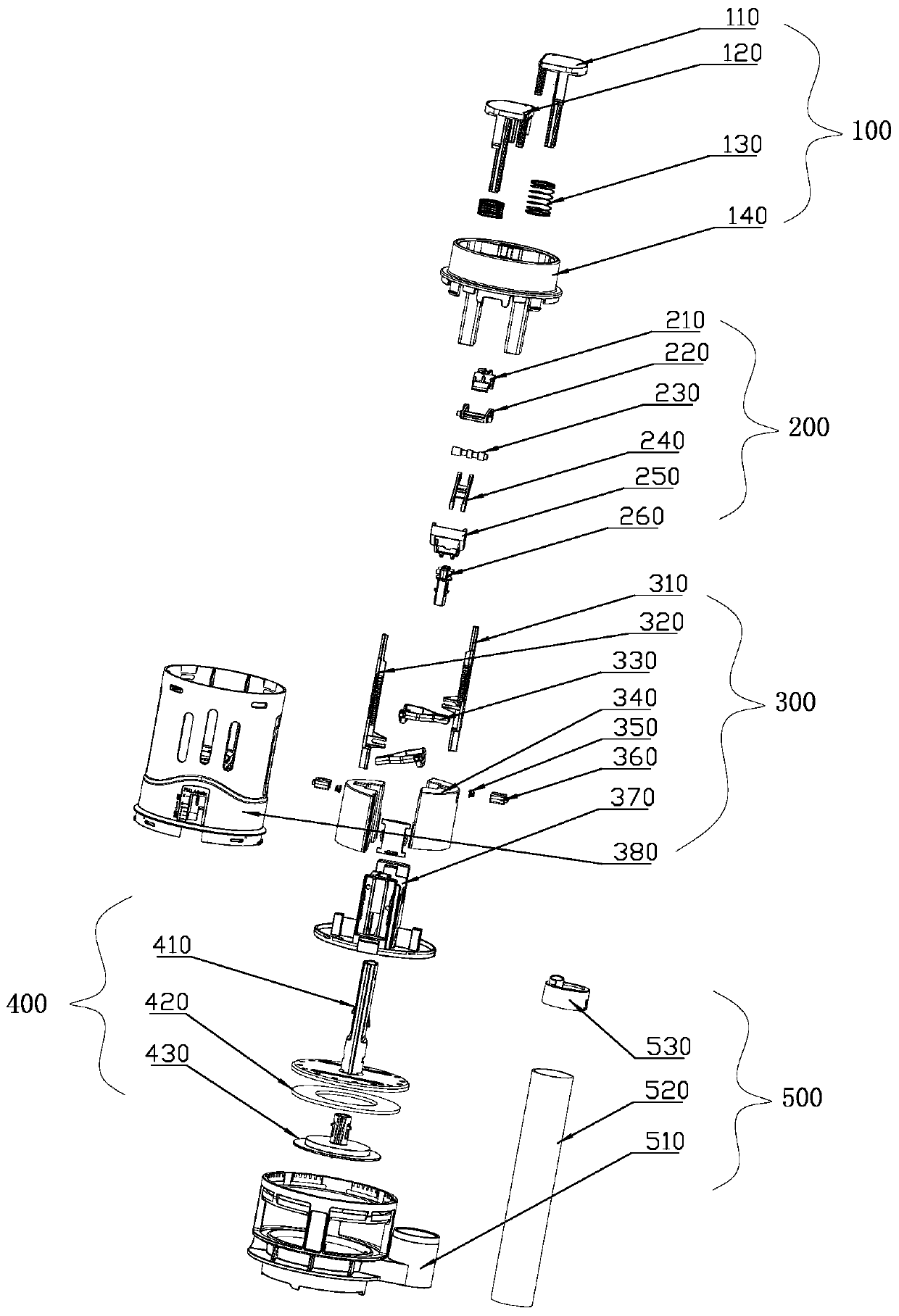
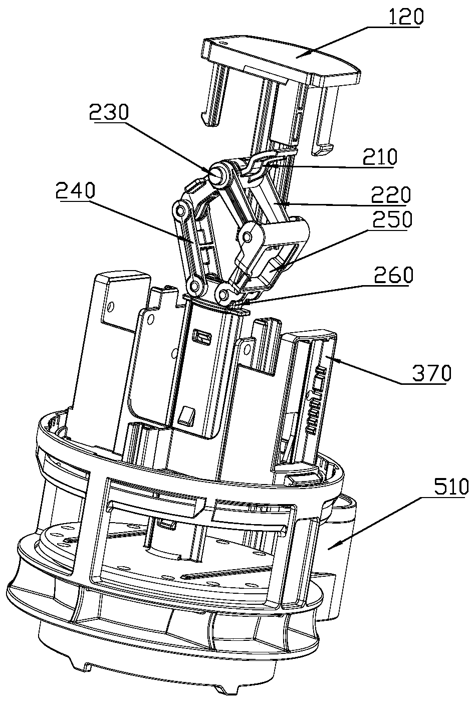
[0028] Such as Figure 1 to Figure 7 As shown, a central force balance drain valve lifting mechanism of the present invention is arranged in the drain valve, and the drain valve includes a button assembly 100, a lifting mechanism 200, a buoy assembly 300, a sealing disc assembly 400, and a base assembly 500, the buoy assembly 300 is installed on the base assembly 500, the button assembly 100, the lifting mechanism 200 and the sealing disc assembly 400 are sequentially installed in the buoy assembly 300 and interlocked.

[0029] The button assembly 100 ...


PUM


Abstract

The invention discloses a central force balanced drainage valve lifting mechanism. The central force balanced drainage valve lifting mechanism is arranged in a drainage valve, and the drainage valve further comprises a button assembly, the lifting mechanism, a floating cylinder assembly, a sealing disc assembly and a base assembly. The floating cylinder assembly is installed on the base assembly,and the button assembly, the lifting mechanism and the sealing disc assembly are installed in the floating cylinder assembly in sequence and cooperatively linked. The lifting mechanism comprises a first balance arm, a second balance arm, a connecting shaft, a third balance arm, a fourth balance arm and a lifting rod, wherein the middle A of the first balance arm rotationally cooperates with the head D of the second balance arm, the tail portion B of the first balance arm rotationally cooperates with the head F of the third balance arm, the tail portion E of the second balance arm rotationallycooperates with the head H of the fourth balance arm, the tail portion K of the fourth balance arm rotationally cooperates with the tail portion G of the third balance arm and rotationally cooperateswith the head of the lifting rod, the rotational cooperation axes are parallel, and the four-bar linkage lifting mechanism is formed. The structure is stable, and the force is balanced.

Description

technical field [0001] The invention relates to a lifting mechanism, in particular to a drain valve lifting mechanism with balanced central force. Background technique [0002] In the drain valve of the toilet tank, the pressing rod and the lifting rod of the button are located near the central axis of the drain valve. In order to turn the downward force of the button into an upward pulling force, a lever is arranged under the button, and a cross bar is arranged on the top of the lifting rod. The movable connection of the crossbar plays the role of pulling up the lifting rod, which makes room in space, but increases the lateral friction force, causing the button to be pulled and jammed, and the friction force increases after long-term use, which is easy to be stuck die. Contents of the invention [0003] The technical problem to be solved by the present invention aims at the above-mentioned deficiencies in the prior art. Provided is a drain valve lifting mechanism with c...

Claims


Application Information

Patent Timeline
Patent Type & Authority Applications(China)
IPC IPC(8): E03D5/092E03D1/35
CPCE03D5/092E03D1/35
Inventor 游卫松陈家旭
Owner 广东安百利卫浴科技有限公司
Why Eureka
Try Eureka