
Binding steel bar connecting assembly and connecting method applied to PC component assembly

A technology of connecting components and binding strips, which is applied in the direction of building components, structural elements, building reinforcements, etc., can solve the problems of discontinuous threads on the surface of butt joint steel bars and high fault tolerance rate, so as to avoid joint deformation hazards, high fault tolerance rate, and reduce The effect of factory cost

Pending Publication Date: 2019-06-14
王玉峰
View PDF16 Cites 3 Cited by
  • Summary
  • Abstract
  • Description
  • Claims
  • Application Information

AI Technical Summary

Problems solved by technology

The present invention has a high error tolerance rate during butt alignment, and is suitable for correcting the deviation of the end of the butt steel bar from the axis of the sleeve; it is more suitable for the connection of the butt joint problem of discontinuous butt threads on the surface of the butt steel bar caused by the misalignment of the longitudinal ribs of the butt joint and inconsistent joint gaps.

Method used


Image

  • Binding steel bar connecting assembly and connecting method applied to PC component assembly
  • Binding steel bar connecting assembly and connecting method applied to PC component assembly
  • Binding steel bar connecting assembly and connecting method applied to PC component assembly

Examples


Embodiment Construction

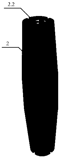
[0040] The present invention is a tie bar type steel bar connection assembly, such as Figure 6 , Figure 7 As shown, it is mainly composed of a combined inner sleeve core 1, a combined middle sleeve 2 and an outer hoop 3 layers tightly enclosed at the ends of two butt steel bars 4. The above three connecting components can all be metal material. Such as figure 1 , figure 2 As shown, the combined inner layer core 1 is composed of two pairs of semicircular tubes ≦1 / 2 round respectively fastened to the ends of two butt steel bars 4, and the inner side of the semicircular tubes is inclined to the outer surface of the butt steel bars 4. Groove 1.1 in which the rib of the transverse thread coincides. Such as image 3 , Figure 4 As shown, the combined middle casing 2 is surrounded by arc-shaped slats that are divided into three to four equal parts in the radial direction of the circumference, and the inner diameter is equal at all places. Variable cross-section combined pip...


PUM


Abstract

The invention relates to a binding steel bar connecting assembly and a connecting method applied to PC component assembly, and belongs to the field of construction engineering. The binding steel bar connecting assembly is formed by closely enclosing the ends of two butt-jointed steel bars with a combined-type inner layer sleeve core, a combined-type middle layer sleeve and an outer sleeve hoop layer; the inner layer sleeve core is composed of two pairs of semi-circular tubes which are correspondingly fastened to the ends of two butt-jointed steel bars, wherein each semi-circular tube is less than or equal to 1 / 2 of a circle, and grooves are formed in the inner sides of the semi-circular tubes, wherein the grooves coincide with oblique transverse thread flanges on the outer surfaces of thebutt-jointed steel bars; the middle layer sleeve is combination pipe with vertical seams and variable cross sections, the combination pipe is defined by arc-shaped plate strips which are divided intothree-four equal parts in the circumferential radial direction, the inner diameter of the combination pipe is equal everywhere, and the outer diameter is reduced from the middle section to both ends;outer layer sleeve hoops are a pair of taper sleeves, wherein each of the inner diameter gradients of the taper sleeves is matched with the outer diameter gradient of the middle layer sleeve, and thetaper sleeves can be sleeved with the two ends of the middle layer sleeve; the distance between the two sleeve hoops is forcibly shortened by special tools, and the inner diameter of the combined-typemiddle layer sleeve is enabled to be reduced, so that the friction and the bond stress at the end of a steel bar are obtained, and thus an effective steel bar joint is obtained.

Description

technical field [0001] The invention relates to the technical field of steel bar butt joint connection in the field of construction, in particular to a tie type assembly for steel bar connection, and a connection method specifically applied to the assembly of PC components. Background technique [0002] There are many technical solutions for the butt connection of steel bars in the construction field, such as butt welding connection, sleeve cold extrusion connection, sleeve grouting connection, etc. At present, my country's prefabricated buildings have been in full swing. The core technology of prefabricated buildings is the connection technology of structural nodes, that is, the steel connection technology between PC (precast concrete) components. However, the node connection technology has become the bottleneck of the rapid development of my country's prefabricated buildings, which has seriously affected the promotion process of the national plan. The component connection...

Claims


Application Information

Patent Timeline
Patent Type & Authority Applications(China)
IPC IPC(8): E04C5/16E04G21/14
Inventor 王玉峰崔士启王世诚张洪忠丁一旭王聪聪张丁涛马明石雷付平
Owner 王玉峰
Learn More