A heat dissipation control method, device and charging pile

A control method and charging pile technology, applied in temperature control, circuit devices, battery circuit devices, etc., can solve the problems of low system power utilization and lower output power, so as to reduce power consumption, improve utilization, and ensure high power output effect

Active Publication Date: 2021-03-19
NINGBO SANXING INTELLIGENT ELECTRIC
View PDF12 Cites 0 Cited by
  • Summary
  • Abstract
  • Description
  • Claims
  • Application Information

AI Technical Summary

Problems solved by technology

If the temperature rise is too high, the DC charger will reduce the output power, and the utilization rate of the system power is low

Method used


Image

  • A heat dissipation control method, device and charging pile
  • A heat dissipation control method, device and charging pile
  • A heat dissipation control method, device and charging pile

Examples


no. 1 example

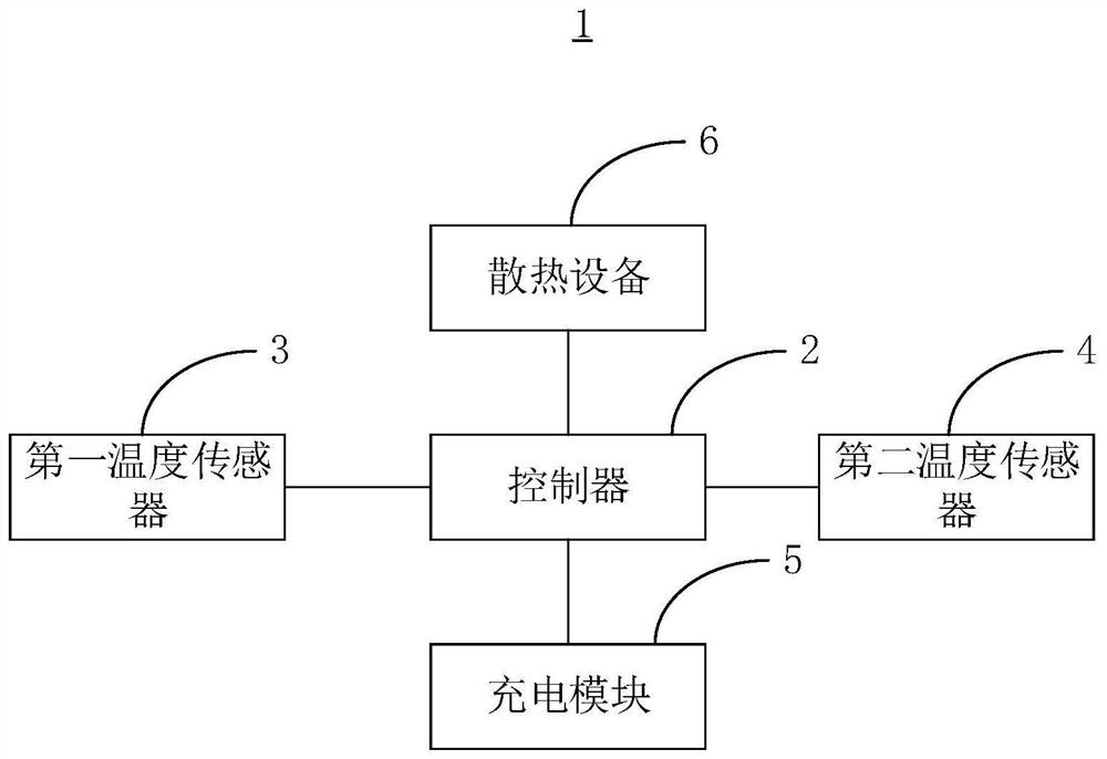
[0031] The embodiment of the present invention provides a heat dissipation control method, which is applied to the charging pile 1, please refer to figure 1 , the charging pile 1 includes a controller 2, a first temperature sensor 3, a second temperature sensor 4, a charging module 5 and a cooling device 6, the controller 2 is connected with the first temperature sensor 3, the second temperature sensor 4, the charging module 5 and the The heat dissipation device 6 is electrically connected, the first temperature sensor 3 is used to obtain the temperature of the air inlet, and the second temperature sensor 4 is used to obtain the temperature of the air outlet. And, in this embodiment, the cooling device 6 is a fan, and its quantity can also be multiple, for example, the quantity of the fan is 3, meanwhile, the quantity of the charging module 5 can also be multiple, such as the quantity of the charging module 5 The number is also three, of course, in some other embodiments, the ...

no. 2 example

[0079] see Figure 6 , is a schematic diagram of functional units of a heat dissipation control device 7 provided by an embodiment of the present invention. It should be noted that the basic principles and technical effects of the heat dissipation control device 7 provided in this embodiment are the same as those of the above-mentioned embodiments. corresponding content in the example. The heat dissipation control device 7 includes:

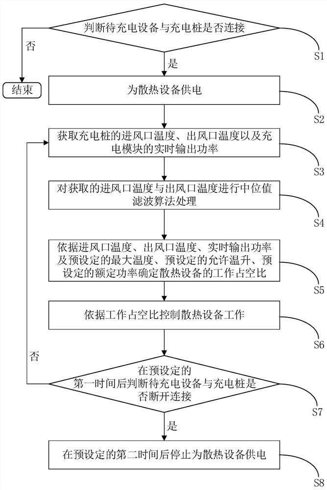
[0080] The judging unit 8 is configured to judge whether the device to be charged is connected to the charging pile 1 or not.

[0081] It can be understood that S1 can be executed by the judging unit 8 .

[0082] The power supply unit 9 is used to supply power to the cooling device 6 .

[0083] It can be understood that S2 can be executed by the power supply unit 9 .

[0084] The information acquisition unit 10 is configured to acquire the temperature of the air inlet and outlet of the charging pile 1 and the real-time output power of the ch...

no. 3 example

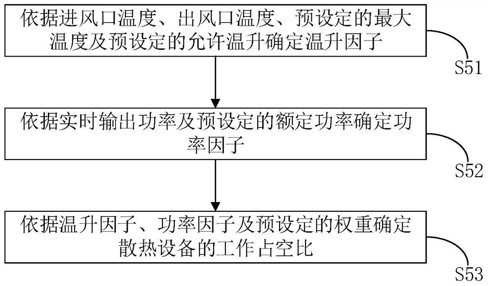
[0104] The embodiment of the present invention also provides a charging pile. The charging pile includes a controller, a first temperature sensor, a second temperature sensor, a charging module, and a heat dissipation device. The controller is connected with the first temperature sensor, the second temperature sensor, the charging The module and the cooling device are electrically connected, the first temperature sensor is used to obtain the temperature of the air inlet, and the second temperature sensor is used to obtain the temperature of the air outlet. Among them, the controller is used to supply power to the cooling device when the device to be charged is connected to the charging pile; and obtain the air inlet temperature, the air outlet temperature of the charging pile, and the real-time output power of the power supply module; The air outlet temperature, real-time output power, preset maximum temperature, preset allowable temperature rise, and preset rated power determi...


PUM


Abstract

The invention provides a heat dissipation control method and device and a charging pile and relates to the technical field of heat dissipation. The method comprises the steps of supplying power to heat dissipation equipment when to-be-charged equipment is connected with the charging pile; obtaining air inlet temperature and air outlet temperature of the charging pile and a real-time output power of the charging module; determining a working duty cycle of the heat dissipation equipment according to the air inlet temperature, the air outlet temperature, the real-time output power, the preset maximum temperature, preset allowable temperature rise and a preset rated power; and controlling the heat dissipation equipment to work according to the working duty cycle. The heat dissipation control method and device and the charging pile provided by the invention specifically have the technical effect of improving a utilization rate of system power.

Description

technical field [0001] The present invention relates to the technical field of heat dissipation, in particular, to a heat dissipation control method, device and charging pile. Background technique [0002] With the development of high-power charging technology, charging facilities will enter a new stage of rapid development. Due to the increase in charging power, the heat generated by the DC charger is also significantly increased. If the temperature rise is too high, the DC charger will reduce the output power, and the utilization rate of the system power will be low. How to balance the relationship between temperature rise and output power is a problem that must be solved for high-power charging. Contents of the invention [0003] The problem solved by the invention is that the utilization rate of system power in the prior art is low. [0004] In order to solve the above problems, in the first aspect, the present invention provides a heat dissipation control method, w...

Claims


Application Information

Patent Timeline
Patent Type & Authority Patents(China)
IPC IPC(8): G05D23/20H02J7/00
Inventor 郭永亮王俭王小博许钢
Owner NINGBO SANXING INTELLIGENT ELECTRIC
Why Eureka
Try Eureka