
High Power Microwave One-dimensional Beam Sweepable Linear Array Antenna

A high-power microwave and linear array technology, which is applied in antenna arrays, antenna arrays that are energized separately, antennas, etc., can solve the problems of reduced radiation efficiency, narrow beam scanning range, and small beam scanning range.

Active Publication Date: 2021-05-18
NAT UNIV OF DEFENSE TECH
View PDF4 Cites 0 Cited by
  • Summary
  • Abstract
  • Description
  • Claims
  • Application Information

AI Technical Summary

Problems solved by technology

[0003] The technical problem to be solved by the present invention is to overcome the narrow scanning range of the existing linear array beam, solve the problem of the decline in radiation efficiency during the beam scanning process, and the problem of small beam scanning range, and can be controlled by a stepping motor in engineering to realize the beam scanning

Method used


Image

  • High Power Microwave One-dimensional Beam Sweepable Linear Array Antenna
  • High Power Microwave One-dimensional Beam Sweepable Linear Array Antenna
  • High Power Microwave One-dimensional Beam Sweepable Linear Array Antenna

Examples


Embodiment Construction

[0039] The specific implementation manner of the present invention will be further described below in conjunction with the drawings and embodiments. The following examples are only used to illustrate the present invention, but not to limit the scope of the present invention.

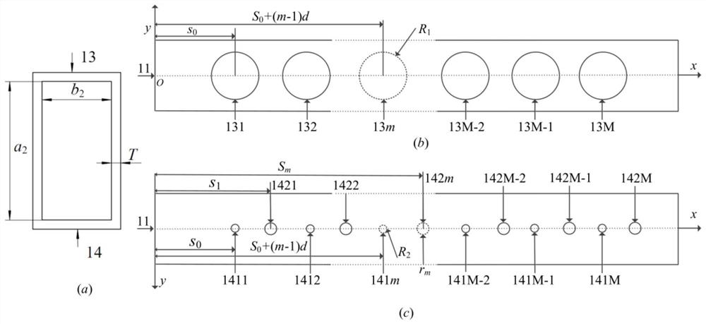
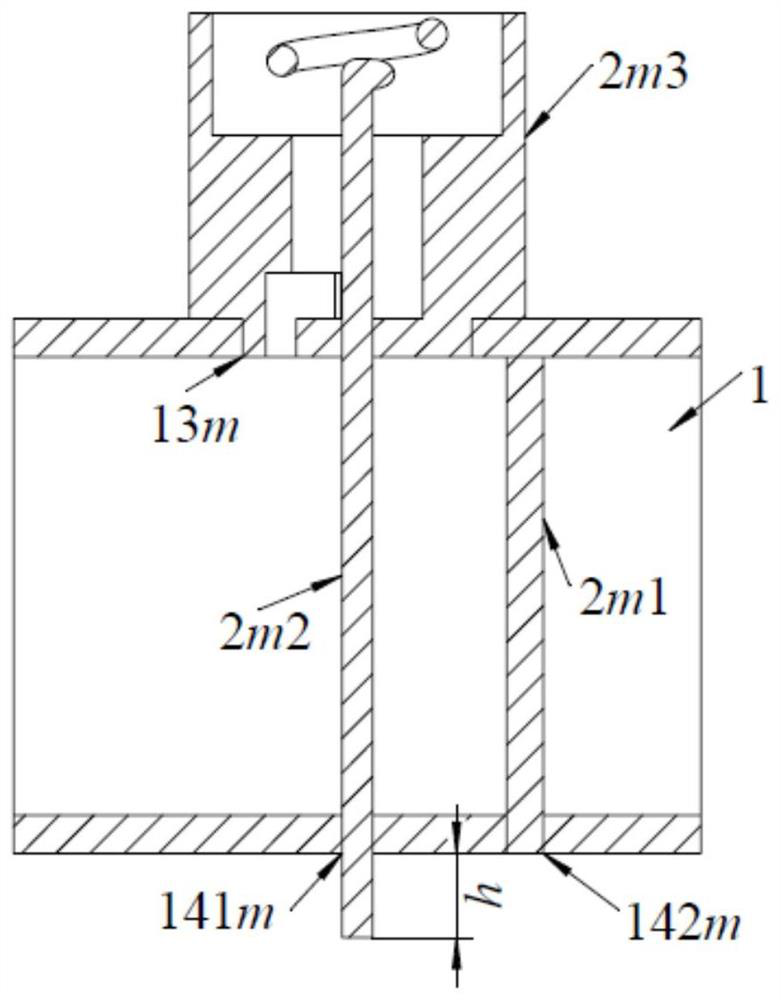
[0040] Such as figure 1 As shown, the present invention is an all-metal structure consisting of two parts, the first part is a rectangular waveguide 1, and the second part is a one-dimensional linear array 2 composed of radiation elements. The microwave is injected from the injection end 11 of the rectangular waveguide, and the output end 12 of the rectangular waveguide is externally connected with a matching load. One-dimensional linear array 2 is composed of M (generally speaking: 20<M<500) radiation units, adjacent radiation units

[0041] The spacing is d (0.5λ<d<λ, where λ is the wavelength of the microwave in free space), and it is installed on the narrow side of the rectangular waveguide along t...


PUM


Abstract

The invention discloses a high-power microwave one-dimensional beam sweepable linear array antenna, aiming at improving the scanning range of the linear array beam and maintaining radiation efficiency. The invention consists of a rectangular waveguide and a one-dimensional linear array; the one-dimensional linear array is composed of M radiation units, and the radiation units are installed on the narrow side of the rectangular waveguide; the radiation unit is composed of a reflection eliminating rod, a helical inner conductor and a coupling cavity; the helical The in-line conductor is inserted into the rectangular waveguide through the coupling cavity, passes through the rectangular waveguide, and is externally connected with a stepping motor. The inner conductor of the helix is ​​composed of a straight cylinder, a semi-circular ring and a section of helix. The spatial orientation angle difference between two adjacent helix inner conductors is a constant. One end of the coupling cavity is a cylindrical boss, and the other end is a cuboid. Inside the coupling cavity Four holes of different shapes are dug, and the rotation angle θ of M coupling cavities m different. The invention can make the scanning range of the beam reach 70 degrees; the radiation efficiency can be kept above 95% in the whole scanning range of the beam, and it is easy to realize in engineering.

Description

technical field [0001] The invention relates to an antenna in the technical field of high-power microwaves, in particular to a high-power microwave antenna with one-dimensional beam scanning capability. Background technique [0002] With the development of pulse power technology and plasma science, high-power microwave sources have obtained microwave pulses with higher frequencies, longer pulses, higher peak power, and higher repetition frequencies, which provides an opportunity to further promote the application of high-power microwave technology. Foundation. The high-power microwave antenna is the terminal of the high-power microwave system, and its performance largely determines the irradiation capability of the high-power microwave system. In the practical application of some high-power microwave systems, it is required that the microwave beam radiated by the antenna can continuously irradiate the moving target, which puts forward the demand for the research of high-pow...

Claims


Application Information

Patent Timeline
Patent Type & Authority Patents(China)
IPC IPC(8): H01Q21/08H01Q21/00H01Q1/36H01Q1/50H01Q3/32
Inventor 袁成卫余龙舟张强孙云飞郝冬青许亮
Owner NAT UNIV OF DEFENSE TECH
Learn More