Antenna structure and antenna array

An antenna structure and antenna body technology, which is applied to antenna arrays, individually powered antenna arrays, and the connection of antenna grounding switch structures, etc., can solve problems that affect user experience and overall product competitiveness, overall wireless performance is unfavorable stability, power consumption, etc. It can improve the data transmission speed, improve the user wireless experience and product competitiveness, and improve the antenna gain.

Active Publication Date: 2021-10-12
ETHETA COMM TECH SHENZHEN CO LTD
View PDF9 Cites 0 Cited by
  • Summary
  • Abstract
  • Description
  • Claims
  • Application Information

AI Technical Summary

Problems solved by technology

The millimeter-wave frequency band has multiple different frequency bands, so broadband or multi-frequency millimeter-wave antennas are the mainstream demand, and the existing broadband millimeter-wave antennas generally have a multi-port structure (that is, more than one port), so their power consumption and heat generation Both are high, so it is unfavorable to the power consumption of the overall system and the stability of the overall wireless performance, which in turn affects the user experience and the overall competitiveness of the product

Method used


Image

  • Antenna structure and antenna array
  • Antenna structure and antenna array
  • Antenna structure and antenna array

Examples


Embodiment 1

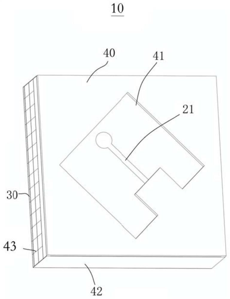
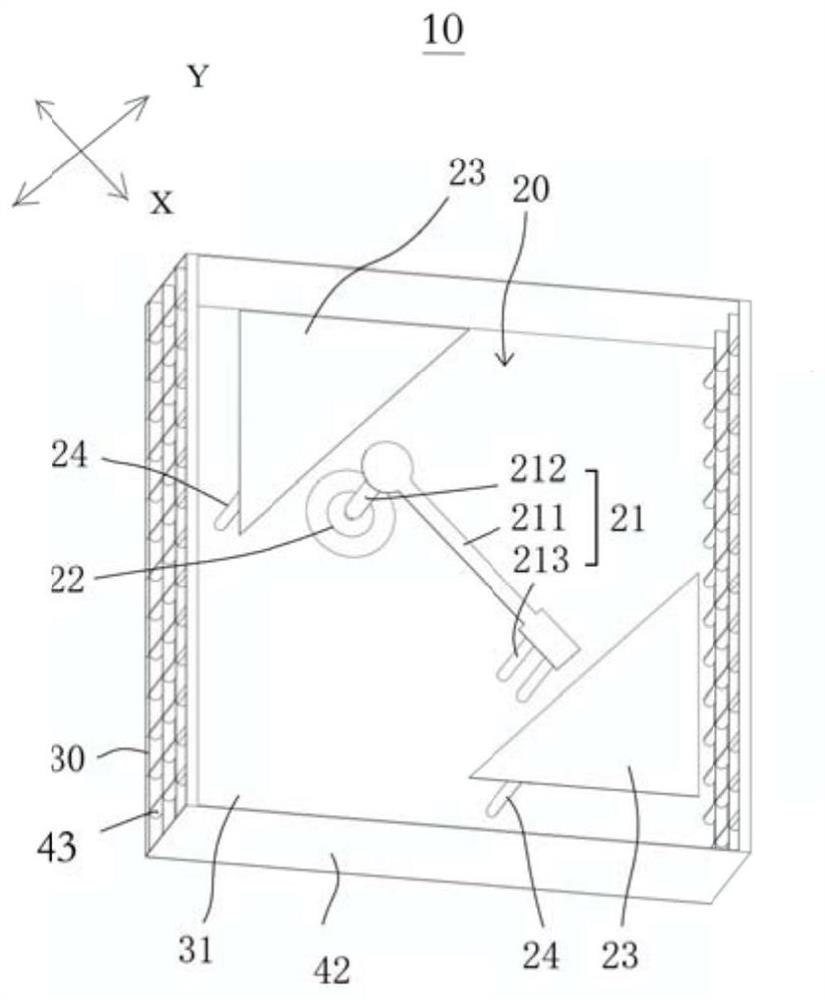
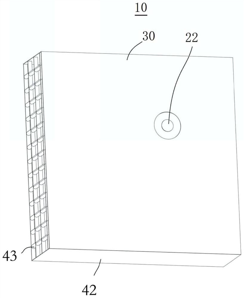
[0066] See figure 1 , figure 2 and image 3 , figure 1 It is a perspective view of the antenna structure 10 provided in the embodiment of the present application, figure 2 Yes figure 1 The stereoscopic map of the antenna structure hides the filler medium, image 3 Yes figure 2 An antenna structure hides another angle after the filler medium. The antenna structure 10 includes a first antenna assembly 20, a carrier 30, and a filler medium 40. The first antenna assembly 20 is disposed on the carrier 30, the filling medium 40 disposed on the carrier 30 and covers at least a portion of the first antenna assembly 20.

[0067] The first antenna assembly 20 includes a first stereo antenna 21 that is grounded or connected to the reference potential, and a single antenna port 22 connected to the other end of the first stereo antenna and the first three-dimensional antenna 21 set. Parasitic structure 23. It will be appreciated that the first stereo antenna 21 is a conductor. The first stereo a...

Embodiment 2

[0084] See Figure 5 , Figure 5 It is a perspective view of the antenna structure 10 provided by the second embodiment of the present application to hide the filler medium. The antenna structure 10 in the second embodiment is substantially the same as the antenna structure 10 in the first embodiment, that is, the description of the antenna structure 10 of the above-described embodiment may be substantially applicable to the antenna structure 10 of Example 2, and below The different points of the antenna structure 10 and the embodiment one of the first embodiment will be mainly described.

[0085] In the second embodiment, the antenna main body 211 includes a first connecting portion 2111 connected to the feed portion 212, and the second connection portion 2113 of the bending portion 213 is connected, and connected to the first connection portion 2111 and the second connection. The main body portion 2112 between the portion 2113. The main body portion 2113 extends in the direction X...

Embodiment 3

[0087] See Image 6 , Image 6 It is a perspective view of the antenna structure 10 provided by the third embodiment of the present application to hide the filler medium. The antenna structure 10 in the third embodiment is substantially the same as the antenna structure 10 in the first embodiment, that is, the description of the antenna structure 10 of the above-described embodiment may be substantially applicable to the antenna structure 10 of the third embodiment, below. The different points of the antenna structure 10 and the embodiment one of the first embodiment will be mainly described.

[0088] In the third embodiment, the first stereo antenna 21 has a bending portion 213, and the bending portion 213 can be coupled between the antenna body 21 and the reference ground plane 31. It will be appreciated that by one of the bending portions 213 facilitates the reduction of manufacturing complexity.


PUM


Abstract

Embodiments of the present invention provide an antenna structure and an antenna array. The antenna structure includes a first antenna component, the first antenna component includes a first three-dimensional antenna with one end grounded or connected to a reference potential, a single antenna port connected to the other end of the first three-dimensional antenna, and a single antenna port adjacent to the first three-dimensional antenna. The first parasitic structure of the antenna setup. In the antenna structure, the first three-dimensional antenna is only connected to a single antenna port, thereby reducing the number of ports required by the antenna, that is, reducing power consumption from the antenna dimension, thereby reducing heat generation at the same time, to maintain stable overall antenna performance , at the same time, through the first parasitic structure arranged adjacent to the first three-dimensional antenna, the first antenna component can cover multi-band and broadband bands, such as multi-band and broadband 5G millimeter wave bands, which can significantly improve user experience and product quality. Comprehensive Competitiveness.

Description

Technical field [0001] Technical Field The present invention relates to an antenna, more particularly to an antenna structure and an antenna array. Background technique [0002] Today, well into 5G (fifth generation mobile communication) era, and 5G communications sub-millimeter wave band and has a non-millimeter wave band. A plurality of millimeter wave band different frequency bands, so that broadband antenna or millimeter wave frequency demand mainstream, whereas conventional antennas typically millimeter-wave broadband multi-port structure (i.e., more than one port), so the power consumption and heat are higher, so the stability of the overall wireless performance and power consumption of the overall system are less favorable, thereby affecting the user's experience with the product's comprehensive competitiveness. Inventive content [0003] In view of this result, there is a need to provide an antenna structure and an antenna array in order to improve the above problems. ...

Claims


Application Information

Patent Timeline
Patent Type & Authority Patents(China)
IPC IPC(8): H01Q1/36H01Q1/50H01Q21/00
CPCH01Q1/36H01Q1/50H01Q21/00H01Q1/40H01Q1/526H01Q9/42H01Q21/08H01Q21/24H01Q5/385H01Q21/0006
Inventor 黄奂衢高大宋漆知行林虹周彦超
Owner ETHETA COMM TECH SHENZHEN CO LTD
Why Eureka
Try Eureka