A cable pulling device

A cable pulling and power supply technology, applied in cable laying equipment and other directions, can solve the problems of heavy index rope, inconvenient transportation, inconvenience, etc., and achieve the effect of convenient replacement of winding rollers, convenient laying, and convenient laying of cables.

Active Publication Date: 2020-07-24
金华八达集团有限公司 +1
View PDF1 Cites 0 Cited by
  • Summary
  • Abstract
  • Description
  • Claims
  • Application Information

AI Technical Summary

Problems solved by technology

[0002] When the outer cable is passed through the pipe, manual and mechanical indexing methods can be used. When transporting the cable index rope at the construction site, it is not convenient to transport due to the heavy weight of the index rope
[0003] The national patent authorization announcement number CN208120470U, the authorization announcement date is 20181120, discloses "a cable traction device", including a frame, a turntable is arranged on the frame, the turntable is connected to the frame in rotation, the lower part of the frame is provided with a moving wheel, and the turntable A left support column and a right support column are symmetrically arranged on the top, and a winding shaft and a front baffle are arranged between the left support column and the right support column. The front baffle is located in front of the winding shaft. The support column and the right support column are hinged, and the front baffle is provided with a moving seat, which is slidably connected with the front baffle, and the left support column is provided with a rotating brush, which corresponds to the winding shaft, and the right end of the winding shaft is set There is a rotating handle, and the rotating handle extends out of the right support column; although the existing technology moves flexibly, when the cable is laid in a straight line, the existing technology tends to deviate, and it is necessary to constantly correct the direction, which is very inconvenient

Method used


Image

  • A cable pulling device
  • A cable pulling device
  • A cable pulling device

Examples


Embodiment Construction

[0021] In conjunction with the accompanying drawings and specific embodiments, the present invention is further elaborated:

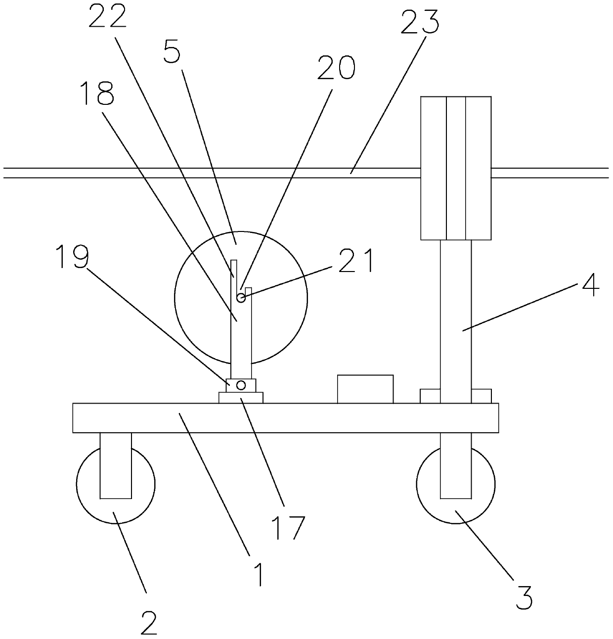
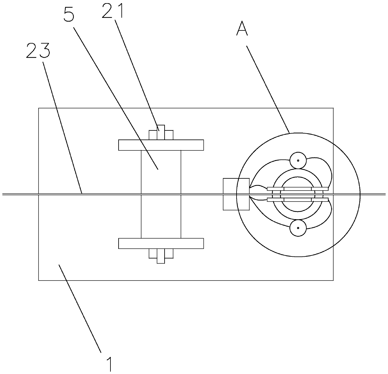
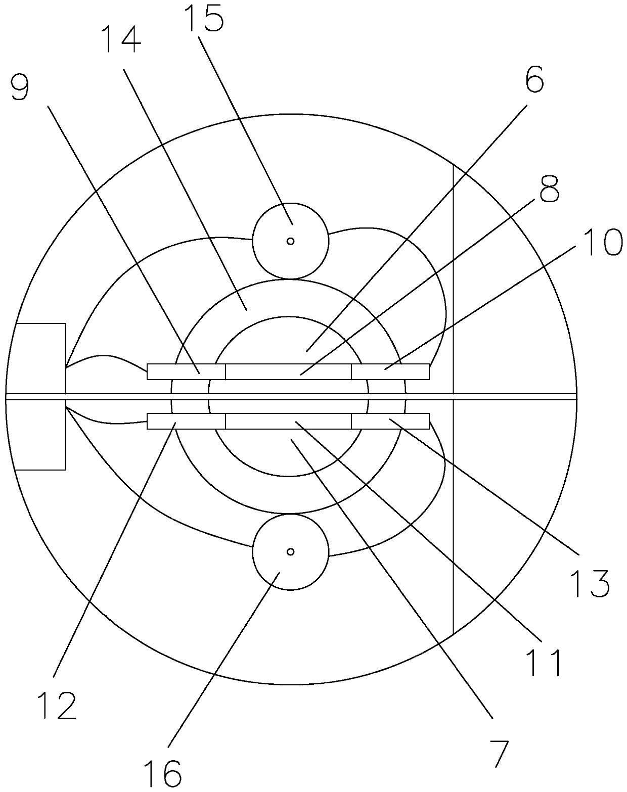
[0022] figure 1 , figure 2 , image 3 , Figure 5 , Figure 6 and Figure 7 It is a cable traction device, including a base 1, two straight wheels 2 and a steering wheel 3 are arranged under the base 1, a steering shaft 4 is inserted on the base 1, and the steering shaft 4 and the base 1 Rotationally connected, the steering wheel 3 is rotatably connected to the bottom end of the steering shaft 4, the base 1 is rotatably connected to a winding roller 5, and the top of the steering shaft 4 is fixedly connected with a first positioning piece parallel to the steering wheel 3 6 and a second positioning piece 7 parallel to the first positioning piece 6, a positioning wire 23 is arranged between the first positioning piece 6 and the second positioning piece 7, and the first positioning piece 6 includes a first insulating sheet 8. One side of the first i...


PUM


Abstract

The invention discloses a cable traction device, and relates to the field of a cable laying device. The cable traction device comprises a base, wherein a straight wheel and a steering wheel are arranged below the base, a steering shaft is inserted onto the base, a winding roller is rotatably connected with the base, a first positioning sheet and a second positioning sheet are fixedly connected with a top end of the steering shaft, a positioning wire is arranged between the first positioning sheet and the second positioning sheet, the first positioning sheet comprises a first insulation sheet,the first insulation sheet is fixedly connected with a first conductive sheet and is fixedly connected with a second conductive sheet, the second positioning sheet comprises a second insulation sheet,the second insulation sheet is fixedly connected with a third conductive sheet and is fixedly connected with the fourth conductive sheet, a driven gear is fixedly connected with the steering shaft, afirst gear and a second gear are engaged with the driven gear, a power supply is arranged on the base, a sliding block is connected with the base in a sliding way, a support is arranged on the sliding block, a connection sheet is fixedly connected with the sliding block, a groove is formed in a top end of the support, a rotation shaft is arranged on the winding roller in a penetrating way, and aguide rod is fixedly connected with the groove. Linear cable laying is convenient.

Description

technical field [0001] The invention belongs to the field of cable laying devices, in particular to a cable pulling device. Background technique [0002] When the outer cable is passed through the pipe, manual and mechanical indexing methods can be used. When transporting the cable index rope at the construction site, it is not convenient to transport due to the heavy weight of the index rope. [0003] The national patent authorization announcement number CN208120470U, the authorization announcement date is 20181120, discloses "a cable traction device", including a frame, a turntable is arranged on the frame, the turntable is connected to the frame in rotation, the lower part of the frame is provided with a moving wheel, and the turntable A left support column and a right support column are symmetrically arranged on the top, and a winding shaft and a front baffle are arranged between the left support column and the right support column. The front baffle is located in front o...

Claims


Application Information

Patent Timeline
Patent Type & Authority Patents(China)
IPC IPC(8): H02G1/06H02G1/08
Inventor 孔晓峰吴秀松张文杰黄穗金航况建国毛伟民于锦梅
Owner 金华八达集团有限公司
Why Eureka
Try Eureka