An intelligent tree cutting machine

A technology of intelligent tree cutting machine and deceleration motor, which is applied in the field of tree cutting machines, can solve the problems of low safety, cost, and many manpower

Active Publication Date: 2021-02-26
山东未来城建筑工程有限公司
View PDF7 Cites 0 Cited by
  • Summary
  • Abstract
  • Description
  • Claims
  • Application Information

AI Technical Summary

Problems solved by technology

[0003] In order to overcome the disadvantages that hand-held chainsaw felling trees is easy to cause sore hands and requires more manpower, in order to control the direction of tree falling, it needs to be pulled with a rope, and the safety is low, the technical problem to be solved: provide a An intelligent tree cutting machine that saves manpower, can control the direction of trees falling, and has high safety

Method used


Image

  • An intelligent tree cutting machine
  • An intelligent tree cutting machine
  • An intelligent tree cutting machine

Examples


Embodiment 1

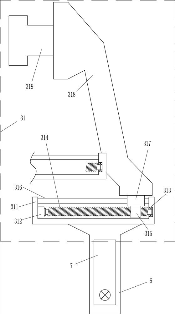
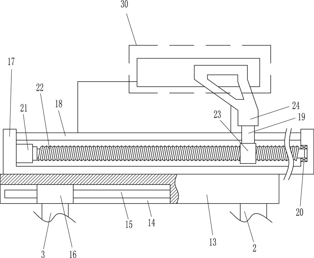
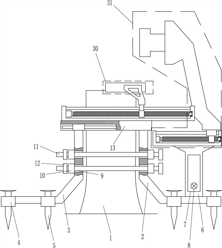
[0018] An intelligent tree cutting machine, such as Figure 1-6 As shown, it includes fixed bracket 2, movable bracket 3, nail sleeve 4, nail 5, support plate 6, control box 7, start indicator light 8, guide sleeve 10, screw rod 11, first nut 12, connecting frame 13, the first A guide rail 15, a first guide sleeve 16, a first N-shaped frame 17, a second guide rail 18, a second guide sleeve 19, a first bearing seat 20, a first reduction motor 21, a first screw rod 22, and a second nut 23 , mounting frame 24, cutting device 30 and tree pushing device 31, movable support 3 is positioned at the left side of fixed support 2, and the left and right sides of the bottom of fixed support 2 and movable support 3 are embedded with nail sleeve 4, is provided with nail in the nail sleeve 4 5. The upper right side of the fixed bracket 2 is connected with a support plate 6, and the fixed bracket 2 is connected with the support plate 6 through bolt connection. The front side of the support pl...

Embodiment 2

[0020] An intelligent tree cutting machine, such as Figure 1-6As shown, it includes fixed bracket 2, movable bracket 3, nail sleeve 4, nail 5, support plate 6, control box 7, start indicator light 8, guide sleeve 10, screw rod 11, first nut 12, connecting frame 13, the first A guide rail 15, a first guide sleeve 16, a first N-shaped frame 17, a second guide rail 18, a second guide sleeve 19, a first bearing seat 20, a first reduction motor 21, a first screw rod 22, and a second nut 23 , mounting frame 24, cutting device 30 and tree pushing device 31, movable support 3 is positioned at the left side of fixed support 2, and the left and right sides of the bottom of fixed support 2 and movable support 3 are embedded with nail sleeve 4, is provided with nail in the nail sleeve 4 5. The support plate 6 is connected to the upper right side of the fixed bracket 2, and the control box 7 is installed on the front side of the support plate 6. The control box 7 includes a power module, ...

Embodiment 3

[0023] An intelligent tree cutting machine, such as Figure 1-6 As shown, it includes fixed bracket 2, movable bracket 3, nail sleeve 4, nail 5, support plate 6, control box 7, start indicator light 8, guide sleeve 10, screw rod 11, first nut 12, connecting frame 13, the first A guide rail 15, a first guide sleeve 16, a first N-shaped frame 17, a second guide rail 18, a second guide sleeve 19, a first bearing seat 20, a first reduction motor 21, a first screw rod 22, and a second nut 23 , mounting frame 24, cutting device 30 and tree pushing device 31, movable support 3 is positioned at the left side of fixed support 2, and the left and right sides of the bottom of fixed support 2 and movable support 3 are embedded with nail sleeve 4, is provided with nail in the nail sleeve 4 5. The support plate 6 is connected to the upper right side of the fixed bracket 2, and the control box 7 is installed on the front side of the support plate 6. The control box 7 includes a power module,...


PUM


Abstract

The invention relates to a tree cutting machine, in particular to an intelligent tree cutting machine. The technical problem to be solved: provide an intelligent tree cutting machine that saves manpower, can control the falling direction of trees, and has high safety. The technical solution is: an intelligent tree cutting machine, including a fixed bracket, a movable bracket, a nail sleeve, nails, a support plate, a control box, etc.; the movable bracket is located on the left side of the fixed bracket, and the left and right sides of the bottom of the fixed bracket and the movable bracket Built in stud sockets. The present invention can fix the fixed bracket and the movable bracket on the tree through the cooperation of the screw rod and the first nut, and then nails are passed through the nail sleeve and nailed into the ground, so that the device can be fixed to prevent the The shaking of the equipment is inconvenient; the rotation of the first reduction motor drives the cutting device to move to the left, so that the trees can be cut through the cutting device, and there is no need for a hand-held chainsaw to operate, which saves manpower and has high safety.

Description

technical field [0001] The invention relates to a tree cutting machine, in particular to an intelligent tree cutting machine. Background technique [0002] Woodworking often needs to use wood, and wood is obtained from tree processing. First, larger trees need to be felled. At present, people usually hold chainsaws to cut trees. Because chainsaws are relatively heavy, it is easy to hold chainsaws for a long time. It causes sore hands, and requires more manpower, and it is easy to be injured during the tree felling process, and the safety is low; Go up, and then pull in the direction that needs to fall, and when the tree falls, it is easy to cause accidents. Contents of the invention [0003] In order to overcome the disadvantages that hand-held chainsaw felling trees is easy to cause sore hands and requires more manpower, in order to control the direction of tree falling, it needs to be pulled with a rope, and the safety is low, the technical problem to be solved: provide...

Claims


Application Information

Patent Timeline
Patent Type & Authority Patents(China)
IPC IPC(8): A01G23/091
Inventor 陈军炼
Owner 山东未来城建筑工程有限公司
Why Eureka
Try Eureka