A redundant drive parallel machine tool dead point avoidance system and method

A dead point and redundant technology, applied in the field of redundant drive parallel machine tool dead point avoidance system, to achieve the effect of accurate judgment of dead point approach, fast calculation speed and easy acquisition

Active Publication Date: 2020-11-06
NANJING UNIV OF SCI & TECH
View PDF9 Cites 0 Cited by
  • Summary
  • Abstract
  • Description
  • Claims
  • Application Information

AI Technical Summary

Problems solved by technology

[0003] The purpose of the present invention is to provide a system and method for avoiding dead points of redundantly driven parallel machine tools to solve the problem of accurately predicting dead points and avoiding dead points of redundantly driven parallel machine tools

Method used


Image

  • A redundant drive parallel machine tool dead point avoidance system and method
  • A redundant drive parallel machine tool dead point avoidance system and method
  • A redundant drive parallel machine tool dead point avoidance system and method

Examples


Embodiment Construction

[0022] The present invention will be further introduced below in conjunction with the accompanying drawings and specific embodiments.

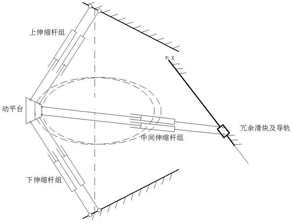
[0023] combine figure 2 , a parallel mechanism in a redundantly driven parallel machine tool, including an upper telescopic rod group, a lower telescopic rod group, a middle telescopic rod group, redundant sliders and guide rails, and four servo motors; one end of the upper telescopic rod group adopts a ball joint fixed, the other end is connected to the top of the moving platform by a ball joint; one end of the lower telescopic rod group is fixed by a ball joint, and the other end is connected to the bottom of the moving platform by a ball joint; one end of the middle telescopic rod group is connected by a ball joint and a redundant slide The blocks are connected, and the other end is connected to the rear of the moving platform by a ball joint; each telescopic rod group is connected to a servo motor, and the servo motor synchronously drives...


PUM


Abstract

The invention discloses a dead point avoiding system and method of a redundant drive parallel machine tool. The system comprises speed measuring generators, photoelectric encoders, a linear sensing synthesizer and a dead point monitoring processor, wherein the speed measuring generators and the photoelectric encoders are connected to servo motors of three telescoping rod groups; the linear sensingsynthesizer is connected to a redundant sliding block; the speed measuring generators are used for acquiring output rotating speed of the servo motors of the three telescoping rod groups; the photoelectric encoders are used for acquiring the rotating circle number of lead screws of the three telescoping rod groups; the linear sensing synthesizer is used for acquiring the position of the redundantsliding block on a guide rail; and the dead point monitoring processor is used for determining whether a parallel mechanism is close to the position of a dead point or not and controlling the telescoping rod groups to telescope as well as controlling the moving direction of the redundant sliding block so as to avoid the position of the dead point. The method comprises the steps of acquiring the output rotating speed of the three telescoping rod groups, the rotating circle number of the lead screws, and the coordinates of the redundant sliding block on the guide rail; calculating the speed ofa movable platform; determining whether the parallel mechanism is close to the position of the dead point or not; and controlling each telescoping rod group and the redundant sliding block to move toavoid the position of the dead point. With the adoption of the system and the method, the dead point can be predicated and avoided.

Description

technical field [0001] The invention belongs to the field of motion control of parallel machine tools, in particular to a redundantly driven parallel machine tool dead point avoidance system and method. Background technique [0002] Since the Stewart mechanism was proposed in the 1960s, the parallel mechanism has been widely used for its advantages of high precision, good dynamic response, and large stiffness-to-weight ratio. As the result of the combination of parallel mechanism and machine tool technology, parallel machine tool is a very efficient modern machining equipment, so the research on parallel mechanism applied to parallel machine tool is more and more important. However, the parallel mechanism has the same dead point position as the traditional mechanism, and because the movement of the parallel mechanism is relatively complicated, the driving rods cooperate with each other and restrict each other, so it is more difficult to accurately predict and avoid the dead ...

Claims


Application Information

Patent Timeline
Patent Type & Authority Patents(China)
IPC IPC(8): B23Q5/00
Inventor 李开明葛帅帅董立磊舒阳张阳
Owner NANJING UNIV OF SCI & TECH
Why Eureka
Try Eureka