
Bearing positioning device and installation method thereof

A positioning device and bearing technology, which is applied in the direction of assembly machines, metal processing equipment, hand-held tools, etc., can solve the problems of low efficiency, reduced service life of bearings, bearings without positioning structures, etc., and achieve strong operability, convenient docking and installation , to ensure the effect of structural stability

Active Publication Date: 2019-06-18
新昌金汇关节轴承有限公司
View PDF6 Cites 0 Cited by
  • Summary
  • Abstract
  • Description
  • Claims
  • Application Information

AI Technical Summary

Problems solved by technology

[0002] Many components are equipped with straight shaft bearings. Because the structure of the straight shaft bearing is small, and the bearing itself has no positioning structure, it is relatively difficult to locate the straight shaft bearing in the axial direction.
[0003] The traditional bearing positioning method is to use tools such as hammers to knock the bearing to make the bearing reach the designated position, but this method is easy to cause damage to the bearing and reduce the service life of the bearing, and the use of knocking for bearing installation may damage the bearing The deflection caused by itself or other parts of the bearing installation position affects the normal operation of the bearing, and the manual positioning of the bearing is low in efficiency and is not conducive to industrial production

Method used


Image

  • Bearing positioning device and installation method thereof
  • Bearing positioning device and installation method thereof
  • Bearing positioning device and installation method thereof

Examples


Embodiment Construction

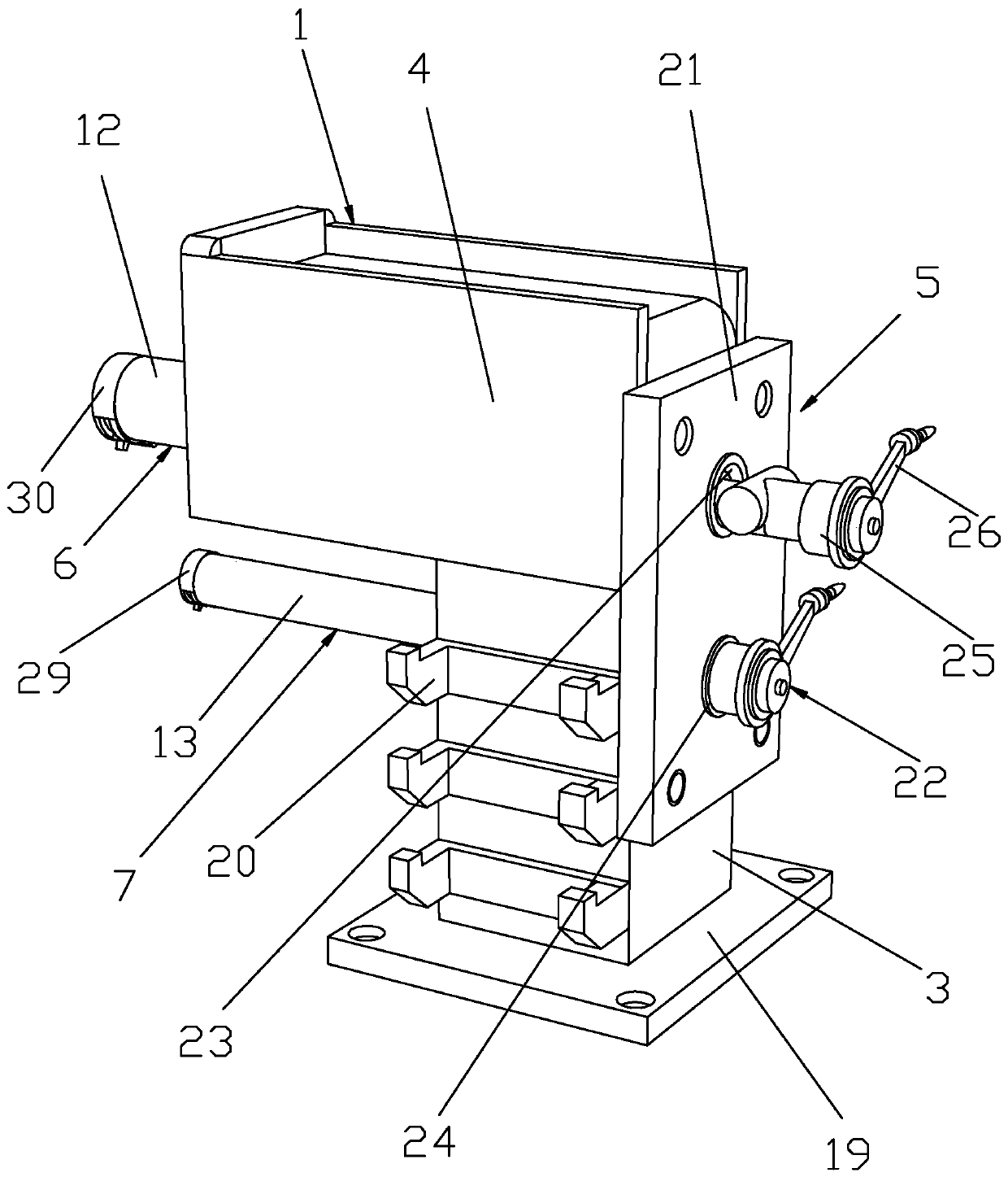
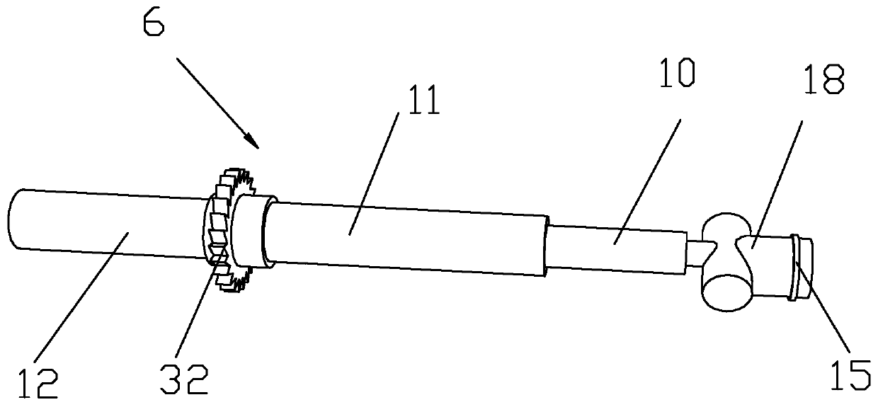
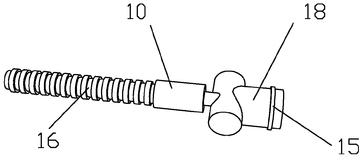
[0040] Such as Figure 1 to Figure 8 As shown, it is a bearing positioning device of the present invention, which includes a main body 1 and a rotating device. The main body 1 includes a vertical component 3 and a horizontal component 4. The angle between the vertical component 3 and the horizontal component 4 is 90°, and the vertical The inside of the part 3 is provided with a lower swirling groove 9, and the inside of the transverse part 4 is provided with an upper swirling groove 8, and the upper swirling groove 8 and the lower swirling groove 9 are arranged in parallel with each other, and the bottom of one end of the transverse part 4 is connected to the vertical part. 3 Fixed connection, the rotating device includes an operating assembly 5, an installation assembly, an upper rotating assembly 6 and a lower rotating assembly 7, the right end of the upper rotating assembly 6 passes through the upper rotating groove 8 and is connected to the operating assembly 5, and the low...


PUM


Abstract

The invention discloses a bearing positioning device. The device comprises a main body and a rotating device; wherein the rotating device comprises an operating assembly, an installing assembly, an upper rotating assembly and a lower rotating assembly; the right end of the rotating assembly penetrates through an upper rotating groove to be connected to the operating assembly, the right end of thelower rotating assembly penetrates through a lower rotating groove to be connected to the operating assembly, the upper rotating assembly comprises an inner rod, a sleeve rod and an ejector rod, the inner rod is arranged on the left side of the sleeve rod, and the right end part of the sleeve rod is fixedly connected to a transverse part. The installation method of the bearing positioning device comprises the following steps of 1), assembling the main body; 2), installing the operating assembly, the upper rotating assembly and the lower rotating assembly; 3), installing the installing assembly; and 4), installing the operating assembly. The device and the method has the advantages that the damage to the bearing can be prevented, the rapid positioning of the bearing is ensured, the deviation is small, the service life of the bearing is prolonged.

Description

technical field [0001] The invention belongs to the field of bearing production, and in particular relates to a bearing positioning device and an installation method thereof. Background technique [0002] Many components are equipped with straight shaft bearings. Because the structure of the straight shaft bearing is small and the bearing itself has no positioning structure, it is relatively difficult to locate the straight shaft bearing in the axial direction. [0003] The traditional bearing positioning method is to use tools such as hammers to knock the bearing to make the bearing reach the designated position, but this method is easy to cause damage to the bearing and reduce the service life of the bearing, and the use of knocking for bearing installation may damage the bearing The deflection is caused by itself or other parts of the bearing installation position, which affects the normal operation of the bearing, and the manual positioning of the bearing is inefficient,...

Claims


Application Information

Patent Timeline
IPC IPC(8): B25B27/02B23P21/00
Inventor 覃祖明向东唐自祥
Owner 新昌金汇关节轴承有限公司
Learn More