An auxiliary conveying device for a double-layer cloth rear beam roller of a textile machine

A technology for textile machinery and conveying devices, which is applied in the field of auxiliary conveying devices for double-layer cloth rear beam rollers of textile machinery, and can solve the problems of affecting the appearance of the cloth, difficulty in breaking free, and the influence of the cloth

Active Publication Date: 2021-05-25
江苏越承纺织科技集团有限公司
View PDF4 Cites 0 Cited by
  • Summary
  • Abstract
  • Description
  • Claims
  • Application Information

AI Technical Summary

Problems solved by technology

[0007] In order to solve the above-mentioned technology, when the equipment is running, the backrest roller will generate heat under high temperature and contact with the airtight layer of the adjacent clothing. The temperature difference is more likely to produce water droplets, and it is difficult to remove the moisture from the bottom layer due to the airtightness. Evaporated, always inside will affect the fabric. When mosquitoes fly in in summer, they are more likely to be entangled by the mesh layer on the surface of the running fabric, and it is difficult to break free. If it is not disposed of in time, it will be together with the mosquitoes. Rolled in together, affecting the appearance of the fabric in the later stage

Method used


Image

  • An auxiliary conveying device for a double-layer cloth rear beam roller of a textile machine
  • An auxiliary conveying device for a double-layer cloth rear beam roller of a textile machine
  • An auxiliary conveying device for a double-layer cloth rear beam roller of a textile machine

Examples


Embodiment

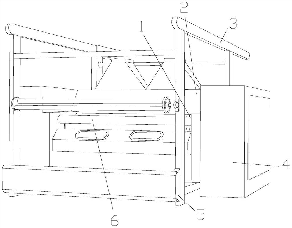
[0032] as attached figure 1 to attach Figure 8 Shown:

[0033] The invention provides an auxiliary conveying device for a double-layer cloth rear beam roller of a textile machine.

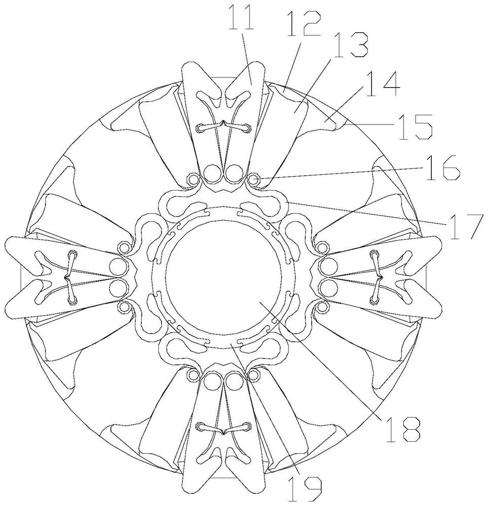
[0034] The rear beam roller device 1 is arranged under the deworming rotary cylinder 2, the deworming rotary cylinder 2 is welded to the outer surface of the operation box 4, the support frame 3 and the bottom support seat 5 are an integrated structure, and the front beam roller 6 is welded with the outer surface of the operation box 4.

[0035] The back beam roller device 1 includes a drip fitting extension rod 11, a sponge body 12, a backup extension rod 13, an extension support plate 14, a movable fixing groove 15, an elastic push column 16, an elastic return plate 17, a central spindle 18, and a reinforcement card. The buckle layer 19, the drip fitting extension rod 11 is located between the sponge bodies 12, the sponge body 12 is installed on the outer surface of the extension rod 13, the ...


PUM


Abstract

The invention discloses an auxiliary conveying device for a double-layer fabric rear beam roller of a textile machine, the structure of which comprises a rear beam roller device, a deworming rotary cylinder, a support frame, an operation box, a bottom support seat, and a front beam roller, and the rear beam roller device is arranged on the dewormer Below the rotating cylinder, the back beam roller device includes a drip fitting extension rod, a sponge body, a spare extension rod, an extension support plate, a movable fixing groove, an elastic push column, an elastic return plate, a central spindle, a reinforced buckle layer, and a drip fitting extension. The rod is located between the sponges. When the internal equipment generates heat through friction, the roller that rolls up the fabric will contact the inner layer of the fabric to form more or less water droplets, and hold it. When mosquitoes are entangled in the When it is on the surface of the grid, the force extruding rod will rotate. When it rotates to the fixed push block, its compression rod will be squeezed, so that the clamping rod will be clamped inward by force. If there are mosquitoes on the surface, it will be Being clamped, waiting for the next operation, it can be clamped on the surface while the equipment is running.

Description

technical field [0001] The invention belongs to the field of textiles, and more specifically relates to an auxiliary conveying device for double-layer fabric rear beam rollers of a textile machine. Background technique [0002] The back beam roller of textile machinery is located in the inner part of the equipment, mainly used to assist in conveying and winding fabrics. Among them, there is a textile machinery double-layer fabric back beam roller auxiliary conveying device. The fabric is bonded together by two layers, and the bottom layer is an air-tight layer. The surface is made of grid-like woven cloth. When the equipment is operated in summer when there are many mosquitoes and high temperature, the temperature inside the equipment will increase. [0003] Based on the above-mentioned inventor's discovery, the existing textile machine backrest roller device mainly has the following deficiencies, such as: [0004] 1. When the equipment is running, the back beam roller will...

Claims


Application Information

Patent Timeline
Patent Type & Authority Patents(China)
IPC IPC(8): B65H20/02
Inventor 潘国堃叶贤良谢杰锋谢云琼
Owner 江苏越承纺织科技集团有限公司
Why Eureka
Try Eureka