A flue gas denitrification device and a flue gas denitrification method

A technology for flue gas and denitrification, which is applied in separation methods, chemical instruments and methods, and gas treatment, etc., can solve the problem that denitration methods are difficult to achieve industrialization, and achieve the effect of reducing airflow resistance and ensuring contact time.

Active Publication Date: 2020-07-31
CHNA ENERGY INVESTMENT CORP LTD +2
View PDF4 Cites 0 Cited by
  • Summary
  • Abstract
  • Description
  • Claims
  • Application Information

AI Technical Summary

Problems solved by technology

[0004] The main purpose of the present invention is to provide a flue gas denitrification device and a flue gas denitrification method to solve the problem of reducing NO in the prior art. x Revert to N 2 The problem that the denitrification method is difficult to achieve industrialization

Method used


Image

  • A flue gas denitrification device and a flue gas denitrification method

Examples


Embodiment 1

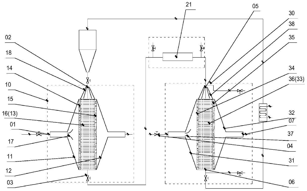
[0048] use figure 1 The shown flue gas denitrification device performs adsorption and reduction treatment on flue gas containing nitrogen oxides in order to achieve denitrification, and uses a chain furnace with a capacity of 0.7 steam tons / hour to generate the flue gas required for treatment.

[0049]The main components of flue gas containing nitrogen oxides are shown in Table 1.

[0050] Table 1

[0051] Element CO NO x

O 2

CO 2

content 0.084wt% 50ppm 16.83wt% 1.99wt%

[0052] Wherein, the catalyst is granular activated carbon with a particle size of 500 μm to 4 mm, and the moving speed of the catalyst in the flue gas adsorption chamber and the moving speed of the catalyst in the flue gas reduction chamber are each independently 0.03 m / s.

[0053] In the flue gas adsorption chamber, the temperature at which the catalyst adsorbs the flue gas is 250°C, the thickness of the catalyst along the flue gas flow direction is 1.5m, and th...

Embodiment 2

[0058] The catalyst is granular activated carbon with a particle diameter of 2 mm to 10 mm, and the rest are the same as in Example 1. Use online flue gas analyzer to detect flue gas import and export NO in real time x concentration, the denitrification rate of flue gas after reduction is 74%.

Embodiment 3

[0060] The moving speed of the catalyst in the flue gas adsorption chamber and the moving speed of the catalyst in the flue gas reduction chamber are each independently 0.6 m / s. Others are with embodiment 1.

[0061] The online flue gas analyzer is used to detect the NOx concentration at the inlet and outlet of the flue gas in real time, and the denitrification rate of the flue gas after reduction is 78%.


PUM

PropertyMeasurementUnit
particle diameteraaaaaaaaaa
thicknessaaaaaaaaaa

Abstract

The invention provides a flue gas denitrification device and method. The flue gas denitrification device comprises a flue gas adsorption unit and a flue gas reduction unit; the flue gas adsorption unit comprises a flue gas adsorption chamber provided with a nitrogen-oxide-containing flue gas inlet, a catalyst inlet and an adsorbed catalyst outlet, the nitrogen-oxide-containing flue gas inlet is located in the side wall of the flue gas adsorption chamber, the catalyst inlet is located in the top wall of the flue gas adsorption chamber, and the adsorbed catalyst outlet is located in the bottom wall of the flue gas adsorption chamber; and the flue gas reduction unit is provided with a flue gas reduction chamber, the flue gas reduction chamber is provided with a reduction gas inlet, an adsorbed catalyst inlet, a catalyst outlet and a nitrogen gas outlet, the reduction gas inlet and the nitrogen gas outlet are formed in the side walls of the flue gas reduction chamber, the adsorbed catalystinlet is formed in the top wall of the flue gas reduction chamber, the catalyst outlet is formed in the bottom wall of the flue gas reduction chamber, and the adsorbed catalyst inlet is connected with the adsorbed catalyst outlet. The denitrification device can be used for reducing NOx into N2 so as to realize industrialization.

Description

technical field [0001] The invention relates to the field of flue gas treatment, in particular to a flue gas denitrification device and a flue gas denitrification method. Background technique [0002] SCR (Selective Catalytic Reduction) and SNCR (Selective Non-Catalytic Reduction) are currently the main technologies for industrial denitrification. SCR uses a vanadium-based catalyst to control the reaction temperature at 300-400°C; since SNCR does not add a catalyst, its reaction temperature is generally 950-1050°C. Since the reducing agent of the two methods is urea or NH 3 , causing a certain amount of ammonia to escape, causing secondary pollution to the environment. [0003] For the problems of high denitrification reaction temperature and ammonia escape, other alternatives have gradually emerged: (1) First, use strong oxidants (such as ozone, sodium hypochlorite, etc.) to remove NO x Oxidation to NO 2 , reuse existing absorbents (such as calcium-based absorbents, etc...

Claims


Application Information

Patent Timeline
Patent Type & Authority Patents(China)
IPC IPC(8): B01D53/90B01D53/56
CPCB01D53/8631B01D53/90B01D2251/202B01D2251/204B01D2251/208B01D2255/20738B01D2255/50B01D2255/702B01D2258/0283Y02C20/10
Inventor 杨春振吴华赵剑
Owner CHNA ENERGY INVESTMENT CORP LTD
Why Eureka
Try Eureka