Double liquid phase groove type distributor

A distributor and two-phase technology, applied in distillation separation, separation method, dispersed particle separation, etc., can solve the problem that the quality of the product cannot meet the requirements, and it can only overflow on the top of the secondary distribution tank, and the product cannot be reached. Quality requirements and other issues, to achieve the effect of easy manufacturing and on-site installation, excellent gas-liquid distribution effect, and a wide range of operating flexibility

Inactive Publication Date: 2008-02-20
TIANJIN UNIV
View PDF0 Cites 8 Cited by
  • Summary
  • Abstract
  • Description
  • Claims
  • Application Information

AI Technical Summary

Problems solved by technology

For example, in some extractive distillations, there are two incompatible liquids, the extract liquid and the reflux liquid. If a general trough liquid distributor is used, stratification will occur in the distributor tank. At this time The heavy phase liquid flows out and distributes through the liquid distribution holes under the secondary distribution tank, while the light phase liquid floats on the heavy phase liquid, which cannot be evenly distributed through the small holes under the secondary distribution tank, and the final result can only be distributed in the secondary distribution tank. The overflow from the top of the tank is randomly distributed, resulting in uneven distribution of the light phase liquid, which in turn affects the mass transfer efficiency and makes the product quality not meet the requirements
For another example, at the feed position in the packed tower, the liquid coming down from above and the feed liquid of the tower enter the first-level main tank of the liquid distributor at the same time. The liquid with a large flow will occupy a dominant position, and can be evenly distributed to the secondary distribution groove below in the first-level main tank, while the liquid with a small flow cannot spread to all the first-level main tanks due to its lower momentum than the liquid with a large flow. The tank can only flow into the secondary distribution tank below near the liquid inlet, so that the liquid with a small flow rate cannot be evenly distributed to the secondary distribution tank below in the primary main tank, which eventually leads to insufficient mixing of the two liquids and The uneven distribution in the filler affects the efficiency of mass transfer and separation, and also fails to meet the product quality requirements

Method used


Image

  • Double liquid phase groove type distributor
  • Double liquid phase groove type distributor
  • Double liquid phase groove type distributor

Examples


Embodiment Construction

[0031] Below in conjunction with accompanying drawing, the present invention will be described in further detail:

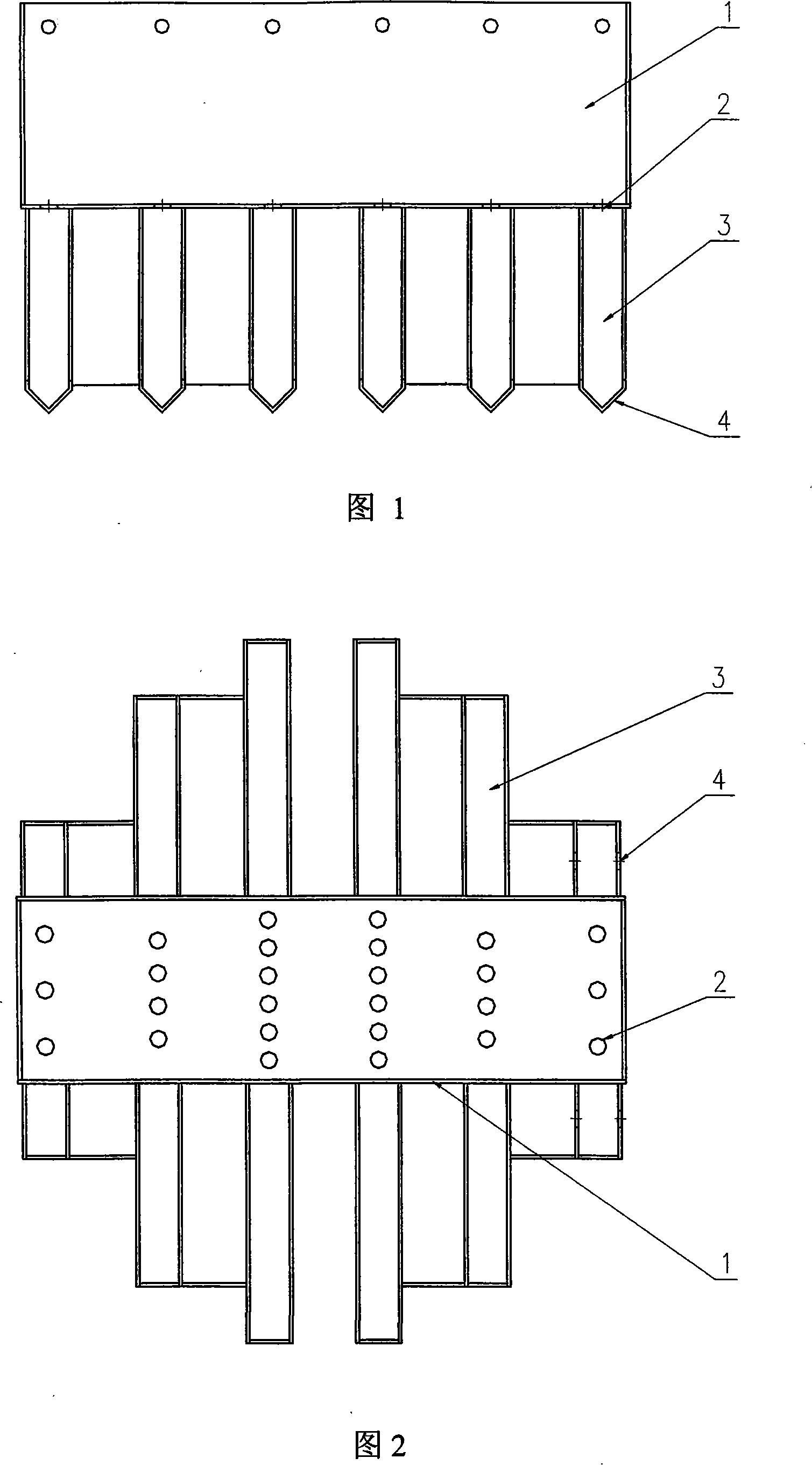
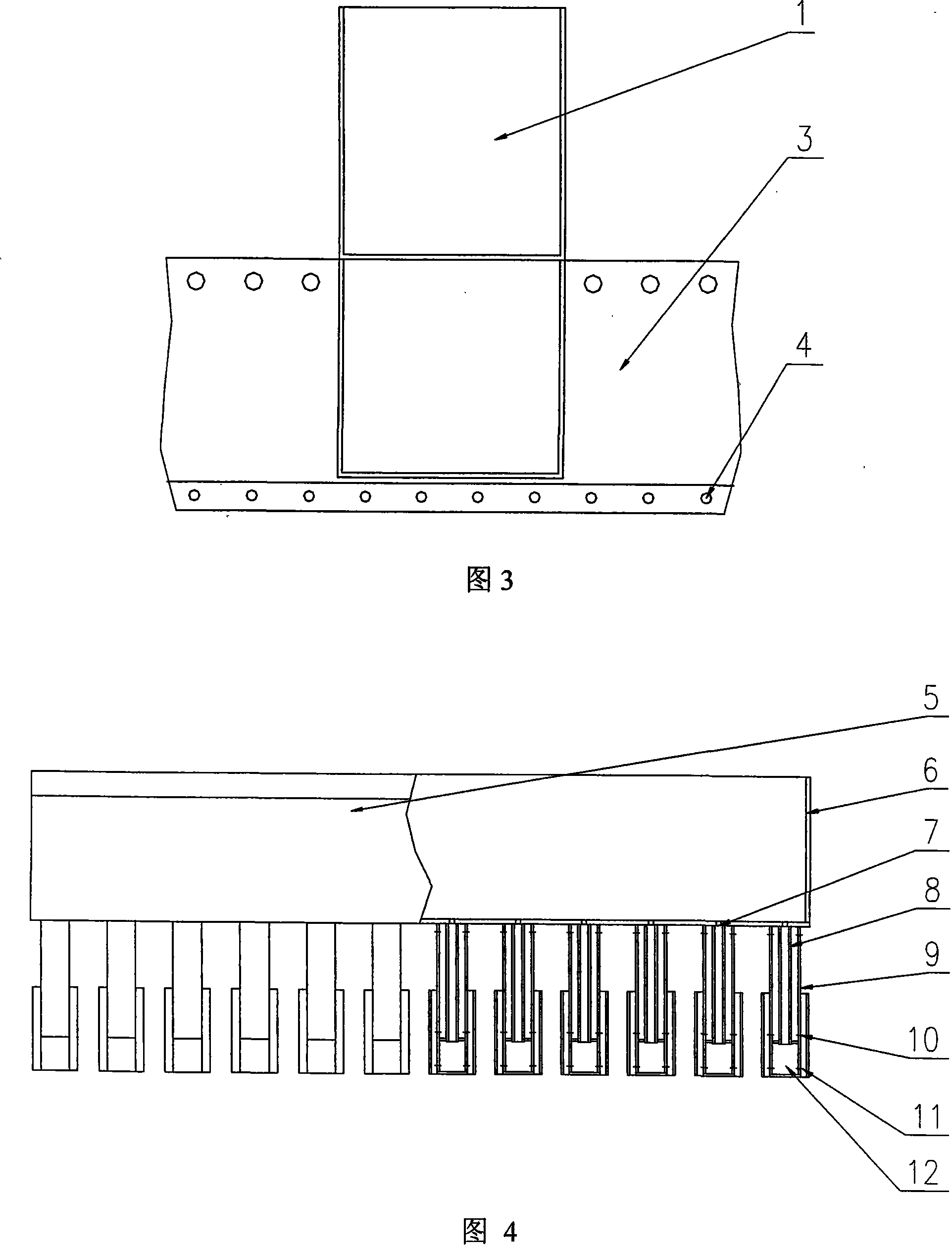
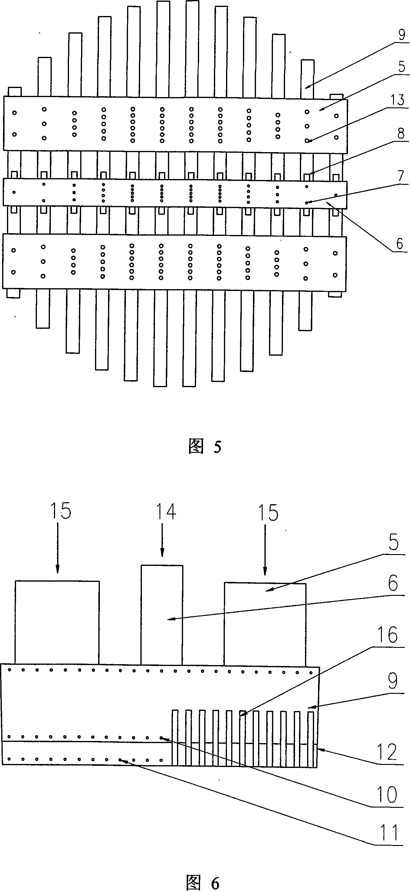
[0032] As shown in Fig. 4, Fig. 5, Fig. 6 and Fig. 7, the present invention is a two-liquid phase trough distributor realized by the following technical scheme. The distributor includes a rectangular first-level main groove and a second-level distribution groove. Below the first-level main groove is a second-level distribution groove arranged in an array perpendicular to it. The first-level main tank is composed of 2 to 4 single-tank boxes, and the second-level distribution tank is composed of two single-chamber tanks that respectively withstand two different liquids. Corresponding to the center position of the secondary distribution tank along the length direction of the first-level main tank body, different numbers of liquid separation holes are opened in proportion to the bottom of the tank body, and the respective liquids are respectively introduced into the ...


PUM


Abstract

The present invention relates to a double fluid phase groove type distributing device comprising a primary main groove and a secondary distributing groove. The primary main groove respectively comprises a heavy phase primary main groove and a slight phase primary main groove, and each primary main groove is provided with one to two. The secondary distributing groove is provided with a heavy phase secondary distributing groove and a slight phase secondary distributing groove. The slight phase secondary distributing groove is connected with the bottom of the heavy phase secondary distributing groove. Besides, the liquid lead tube of the slight phase secondary distributing groove is embedded into the heavy phase secondary distributing groove. The lower part of the side wall of the heavy phase secondary distributing groove is provided with an array or a plurality of arrays of little liquid distributing holes, while the upper part of the side wall is provided with an array of overflows. The lower part of the side wall of the slight phase secondary distributing groove is provided with an array or a plurality of arrays of little liquid distributing holes. The present invention has the advantages of simple structure, few area occupied, low current resistance, low pressure, board operation range and easy production and field mounting. The present invention can be widely used in towers such as a distillation tower, particular a distillation tower, an absorption tower, an adsorption tower and a reaction tower in the fields such as chemical, petrochemical, light industry, pharmacy, fertilizer and environmental protection.

Description

technical field [0001] The invention belongs to the technical field of liquid distributors, in particular to a two-liquid-phase trough distributor. Background technique [0002] The liquid distributor is a vital column internal part of the packed column, which plays an important role in the initial distribution of the liquid. The quality of the initial distribution of the liquid not only affects the end effect of the packing layer, but also affects the entire packing bed, especially the structured packing that has a higher requirement for the initial distribution, which has a greater impact on the entire bed. [0003] Liquid distributors can be divided into pressure type and gravity type according to the power source of liquid outflow. The pressure type liquid distributor relies on the power of the pump for spray distribution, and most of them are pipe distributors; the gravity type liquid distributor relies on the gravity generated by the liquid at a certain height in the ...

Claims


Application Information

Patent Timeline
Patent Type & Authority Applications(China)
IPC IPC(8): B01D3/22B01D53/18
Inventor 何杰孟永祥王涛郭勇义江家贵张桔苹
Owner TIANJIN UNIV
Why Eureka
Try Eureka