Heat pump air conditioner

a technology of heat pump and air conditioner, which is applied in the direction of lighting and heating apparatus, refrigeration components, heating types, etc., can solve the problems of uneven cooling/heating, uneven heating or cooling of air, etc., and achieve stable air conditioning, reduce uneven cooling/heating, and eliminate overshoot

Inactive Publication Date: 2016-01-28
KIMURA KOHKI CO LTD
View PDF11 Cites 7 Cited by
  • Summary
  • Abstract
  • Description
  • Claims
  • Application Information

AI Technical Summary

Benefits of technology

[0015]According to a fifth aspect of the present invention, the controller switches a state of the pair of the compressors between an operating state and an operation stopped state not in a defrosting operation period during a heating operation, but in a period other than the defrosting operation period. Accordingly, in the defrosting operation period during the heating operation, the pair of the compressors does not stop at one time, but the compressors are defrosted alternately. Therefore, the heating operation is not interrupted. Also, it is not necessary to separately install a heater or the like for use in the defrosting operation.
[0016]According to a sixth aspect of the present invention, after causing the second heat pump to start operating, when causing the first heat pump to start operating, the controller controls the operation of the second heat pump to reduce an output of the second heat pump, such that an output of the first heat pump when the first heat pump starts operating is subtracted from the output of the second heat pump, which has already started operating. In this manner, increase / decrease in the outputs of the plurality of heat pumps can be offset, and thereby overshoot can be eliminated. This makes it possible to reduce unevenness in cooling / heating, thereby realizing stable air conditioning.
[0017]According to a seventh aspect of the present invention, in a stop operation of causing an output of the first heat pump to decrease in accordance with elapse of time and then causing an output of the second heat pump to decrease in accordance with elapse of time, the controller controls the operation of the second heat pump such that, when the first heat pump stops operating, the output of the second heat pump increases by an amount corresponding to a decrease in the output of the first heat pump, the decrease occurring immediately before the first heat pump stops operating. In this manner, increase / decrease in the outputs of the plurality of heat pumps can be offset, and thereby undershoot can be eliminated. This makes it possible to reduce unevenness in cooling / heating, thereby realizing stable air conditioning.
[0018]According to an eighth aspect of the present invention, the plurality of first and second heat pumps have different minimum critical powers from each other. For example, assume a case where the ratio of the minimum critical power of the first heat pump to the minimum critical power of the second heat pump is 6:4. In this case, if the air-conditioning load is small, then only the heat pump with a lower minimum critical power, i.e., the second heat pump, may be operated. On the other hand, assume a case where all the heat pumps have the same minimum critical power, for example, the ratio of the minimum critical power of the first heat pump to the minimum critical power of the second heat pump is 5:5. In this case, unlike the case where each heat pump has a different minimum critical power, a suitable operation for a small air-conditioning load cannot be performed. Thus, according to the eight aspect of the present invention, since each heat pump has a different minimum critical power, a suitable operation can be performed even if the air-conditioning load varies widely. This consequently makes it possible to improve the comfortableness and energy efficiency of cooling / heating.
[0019]According to a ninth aspect of the present invention, the heat pump air conditioner further includes a vaporizing humidifier and a steam humidifier. In the heat pump air conditioner, along an air passage, the vaporizing humidifier is disposed downstream of the air-intake-side heat exchanger, and the steam humidifier is disposed downstream of the vaporizing humidifier. The vaporizing humidifier and the steam humidifier are connected to the controller. The controller causes the vaporizing humidifier to humidify intake air, and then if the humidifying of the intake air by the vaporizing humidifier is insufficient, causes the steam humidifier to operate to further humidify the intake air. Accordingly, at the time of humidifying the air, the air conditioner mainly uses the vaporizing humidifier whose running cost is less than that of the steam humidifier. Therefore, by humidifying the air by the vaporizing humidifier first and then compensating for the shortfall of the humidity by the steam humidifier, the cost of humidifying the air can be reduced.
[0020]According to a tenth aspect of the present invention, a cross section of each heat transfer pipe has an ellipsoidal shape. Accordingly, the air flow resistance of the heat transfer pipes is small. Therefore, pressure loss in the air passing by the heat transfer pipes is small. Since the area of contact between the heat transfer pipes and the air passing by the heat transfer pipes can be set to be large, the efficiency of heat exchange between the heat transfer pipes and the air passing by the heat transfer pipes can be improved, which makes it possible to improve the comfortableness and energy efficiency of the cooling / heating.

Problems solved by technology

In this case, when cooling / heating is performed by only one of the heat pumps, the cooling / heating is performed in an uneven manner utilizing only one part of the air-intake-side heat exchanger.
In this case, air passing through the air-intake-side heat exchanger is partly cooled down or heated up, and thereby unevenness occurs in the heating or cooling of the air.

Method used


Image

  • Heat pump air conditioner
  • Heat pump air conditioner
  • Heat pump air conditioner

Examples


embodiment 1

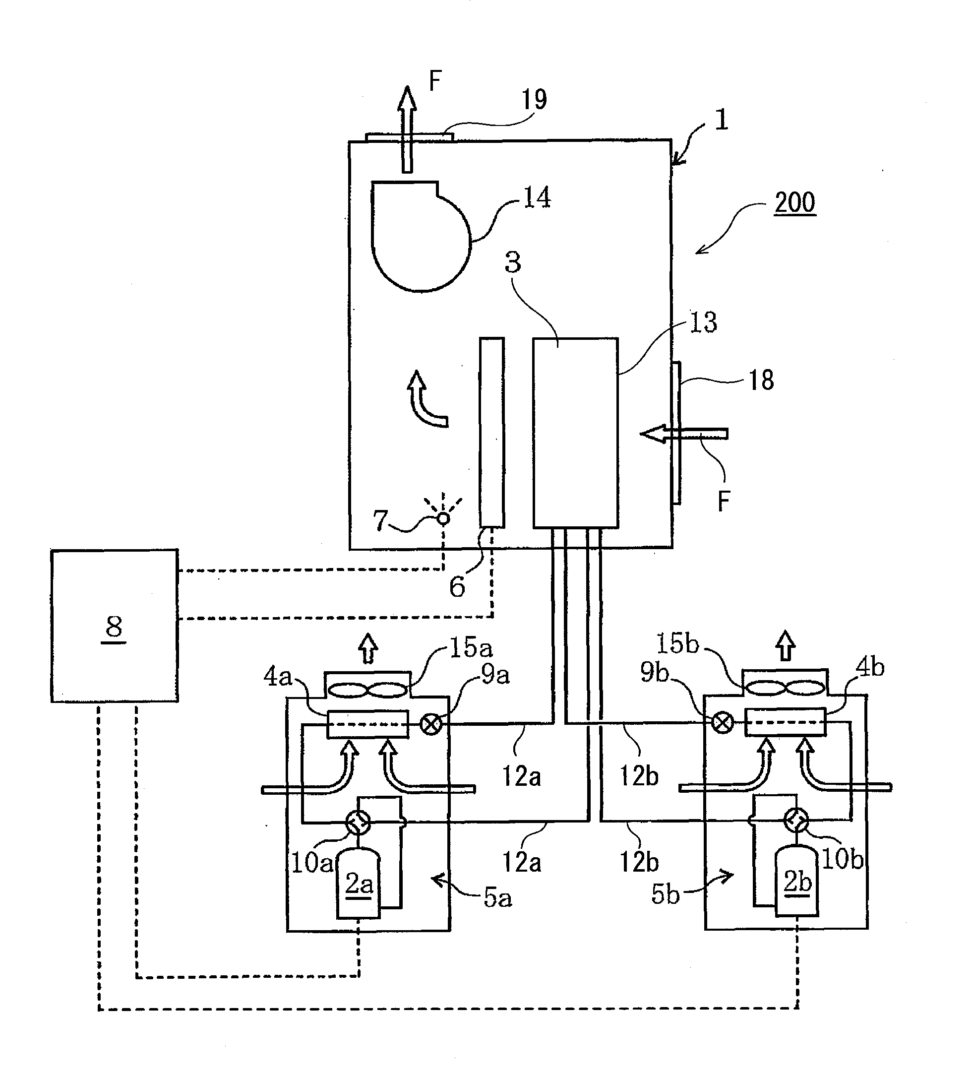
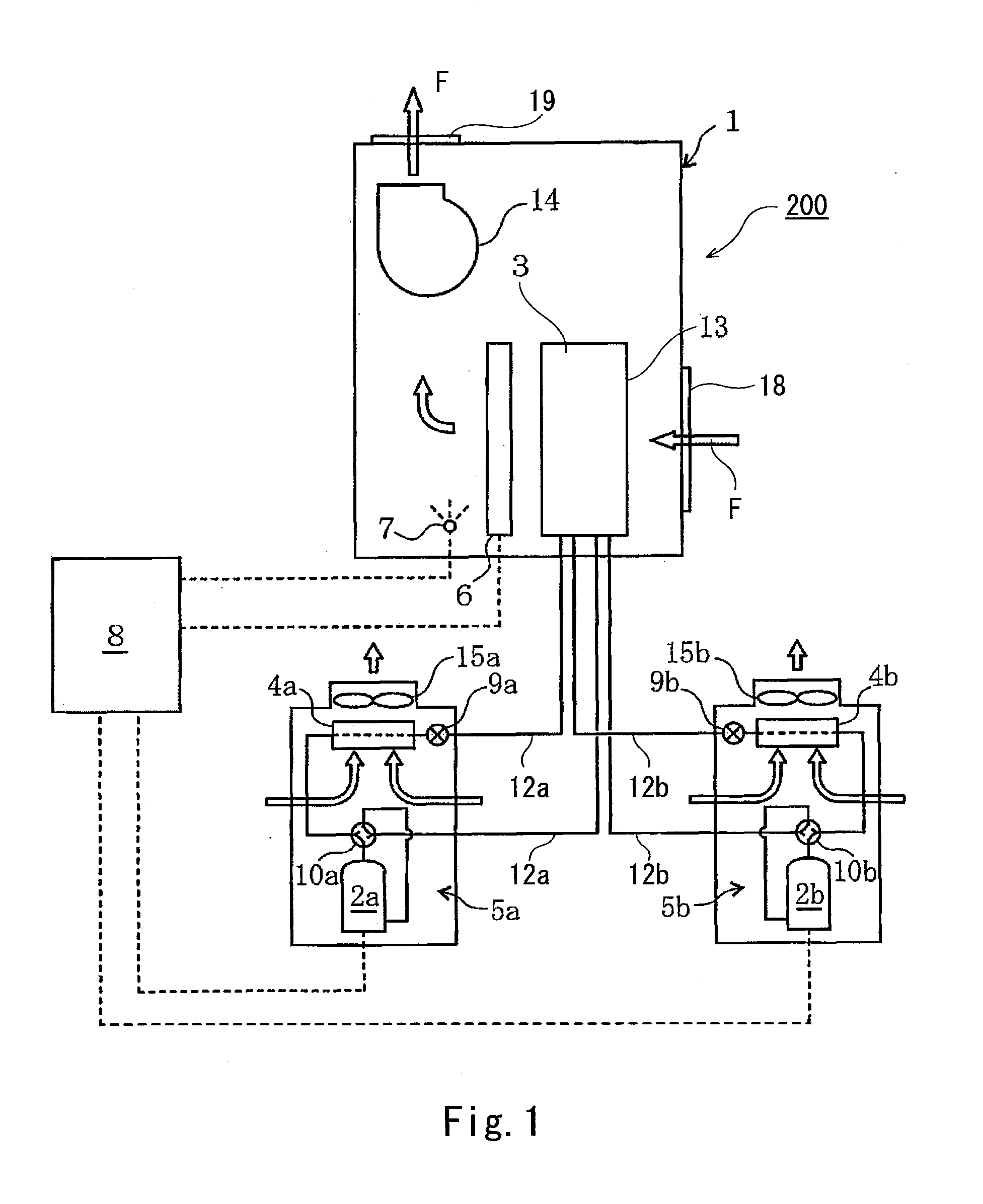
[0041]The controller 8 includes a microprocessor and various sensors, for example. The controller 8 includes a memory as necessary. The controller 8 stores a reference value for an air-conditioning load applied to the heat pump air conditioner 200. The controller 8 compares the air-conditioning load applied to the heat pump air conditioner 200 with the reference value, switches the state of the first compressor 2a and the second compressor 2b between an operating state and an operation stopped state, and performs output adjustment. Specifically, if the air-conditioning load applied to the heat pump air conditioner 200 is less than the reference value, the controller 8 stops both the compressors 2a and 2b from operating.

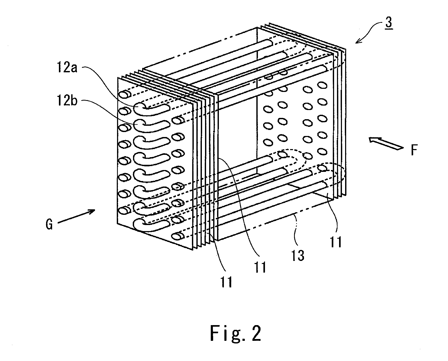
[0042]If the load applied to the heat pump air conditioner 200 is higher than or equal to the reference value and is great, the controller 8 causes both the compressors 2a and 2b to operate, thereby causing the refrigerant to flow into all of the heat transfer pipes 1...

embodiment 2

[0044]If the load applied to the heat pump air conditioner 200 is higher than or equal to the reference value, the controller 8 may cause the first compressor 2a and the second compressor 2b to operate alternately. As a result, the refrigerant flows into the heat transfer pipes 12a and the heat transfer pipes 12b alternately. Specifically, while causing the first compressor 2a to operate, the controller 8 stops the second compressor 2b, thereby stopping the flow of the refrigerant in the second heat transfer pipes 12b, and while stopping the first compressor 2a, the controller 8 causes the second compressor 2b to operate, thereby causing the refrigerant to flow into the heat transfer pipes 12b. The order in which the first compressor 2a and the second compressor 2b are caused to operate alternately may be inverted during the operation. Further, the controller 8 may adopt an operation pattern in which the heat pumps 5a and 5b are sequentially caused, one by one, to start and stop. In...

embodiment 3

[0046]Alternatively, when causing the first compressor 2a and the second compressor 2b to operate alternately, the controller 8 totals either a previous operating time of each of the compressors 2a and 2b or the number of previously performed operations of each of the compressors 2a and 2b. The controller 8 may preferentially cause one of the compressors 2a and 2b with a less previous operating time or a less number of previously performed operations to operate, and may stop the other one of the compressors 2a and 2b with a more previous operating time or a more number of previously performed operations. In this manner, the operation frequency or operating time can be made uniform between the compressors 2a and 2b. This makes it possible to extend the life of the compressors 2a and 2b, and reduce the number of times to repair the compressors 2a and 2b due to breakdown.

[0047]The controller 8 may switch the state of the compressors 2a and 2b between an operating state and an operation...


PUM


Abstract

A heat pump air conditioner includes an intake side heat exchanger including heat transfer pipes passing a refrigerant and being arranged in a direction along an air inlet face, intake heat exchanger configured to cool or warm air and supply the air to a space. A plurality of heat pumps include a plurality of compressors and configured to compress the refrigerant and supply the compressed refrigerant to the heat transfer pipes and a plurality of heat side exchangers and connected to the respective compressors, the heat pumps sharing the air intake side heat exchanger, and a controller configured to switch a state of the compressors and between an operating state and an operation stopped state. The controller controls the compressors and to switch an operation of each of the compressors and between starting and stopping in accordance with a magnitude of an air-conditioning load.

Description

BACKGROUND OF THE INVENTION[0001]1. Field of the Invention[0002]The present invention relates to heat pump air conditioners.[0003]2. Description of the Related Art[0004]As described in Japanese Laid-Open Patent Application Publication No. H09-264614, a conventional heat pump air conditioner includes a compressor, an air-intake-side heat exchanger, and a heat-source-side heat exchanger. The compressor and heat exchangers form a heat pump, and are connected to each other by piping, such that a refrigerant circulates through these devices.[0005]Such a heat pump air conditioner is used throughout the year. In the description below, within one year, a period other than a high-temperature summer period and a low-temperature winter period is referred to as an intermediate period.[0006]In a conventional heat pump air conditioner, the higher the necessary cooling / heating capacity of the heat pump air conditioner, the higher the minimum critical power of the compressor. Therefore, the cooling...

Claims


Application Information

Patent Timeline
Patent Type & Authority Applications(United States)
IPC IPC(8): F25B13/00F25B7/00F25B49/02
CPCF25B13/00F25B49/02F25B7/00F24F5/001F24F13/30F24F2203/021F25B39/00F25B49/022F25B2313/023F25B2400/06F25B2500/26F25B2500/27
Inventor KIMURA, KEIICHIMORITA, MITSUO
Owner KIMURA KOHKI CO LTD
Why Eureka
Try Eureka