Blade turnover transport cart

A technology for transporting vehicles and blades, applied in the direction of lifting devices, lifting frames, etc., can solve the problems of vibrating blade surfaces, blade slippage, blade breakage, etc., and achieve the effect of simplifying operation, improving amplitude and ensuring stability

Inactive Publication Date: 2019-06-18
SHANGHAI KEDONG AUTOMATIC CONTROL ENG
View PDF7 Cites 2 Cited by
  • Summary
  • Abstract
  • Description
  • Claims
  • Application Information

AI Technical Summary

Problems solved by technology

[0002] The existing blade turning device uses the blade root to drive the blade tip, and the two rollers of the blade root drive the blade tip to rotate together. This structure completely relies on friction to drive the blade to move, and the blade will slip when the equipment is used for a long time. As a result, the blades may break; because the equipment drives the blades by friction, when the blades become larger and larger, the friction force will be too small to meet the drive blades; the existing structure of the entire equipment frame is relatively simple, In the process of turning over the blade, it is easy to have a large vibration, which will cause quality defects such as fracture on the surface of the blade

Method used


Image

  • Blade turnover transport cart
  • Blade turnover transport cart
  • Blade turnover transport cart

Examples


Embodiment Construction

[0022] The following description serves to disclose the present invention to enable those skilled in the art to carry out the present invention. The preferred embodiments described below are only examples, and those skilled in the art can devise other obvious variations.

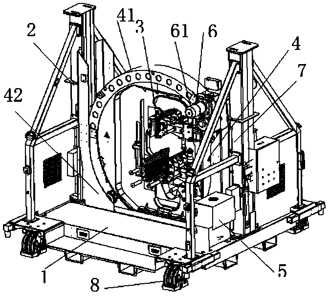
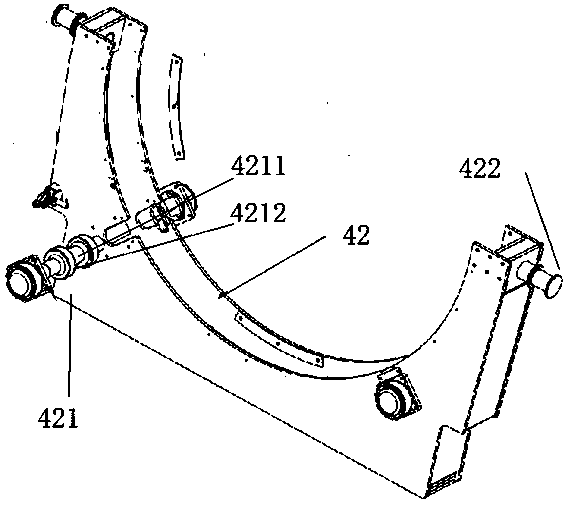
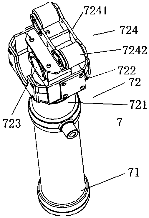
[0023] refer to Figure 1-Figure 6 , a vane overturning transport vehicle, which needs to fix the blade tip and blade root when transporting the blade. This application only relates to the blade overturning transport vehicle for fixing the blade tip. The blade overturning transport vehicle includes a base 1, a column structure 2, and a disc structure 3. Shell structure 4, hydraulic station 5, reducer power structure 6, lifting structure 7 and heavy-duty swivel casters 8.

[0024] The base 1 is used to carry all the installation structures of the blade turning transport vehicle, wherein the lower part of the base 1 is provided with four heavy-duty swivel casters 8, and the four heavy-duty swivel casters 8 ar...


PUM


Abstract

The invention relates to a blade turnover transport cart, which is used for fixing a blade tip of a blade. The blade turnover transport cart comprises a base, two upright post structures, a disc structure, a shell structure, a hydraulic station, a speed reducer power structure and a lifting structure, wherein the upright post structures, the disc structure and the shell structure are arranged on the base, the shell structure is arranged between the two upright post structures, the disc structure is arranged in the shell structure, the disc structure is used for fixing the blade tip of the blade, the shell structure can be lifted in the extension direction of the upright post structures by the lifting structure, and the disc structure can rotate relative to the shell structure by the speedreducer power structure. The posture of the blade can be adjusted by hydraulic power, so that the stability of the whole blade during lifting and descending is guaranteed, and the rotating amplitude of the blade is greatly increased by using a speed reducer.

Description

technical field [0001] The invention relates to a blade turning device, in particular to a blade turning transport vehicle. Background technique [0002] The existing blade turning device uses the blade root to drive the blade tip, and the two rollers of the blade root drive the blade tip to rotate together. This structure completely relies on friction to drive the blade to move, and the blade will slip when the equipment is used for a long time. As a result, the blades may break; because the equipment drives the blades by friction, when the blades become larger and larger, the friction force will be too small to meet the drive blades; the existing structure of the entire equipment frame is relatively simple, During the flipping process of the blade, a large vibration is likely to occur, so that quality defects such as fractures occur on the surface of the blade. Contents of the invention [0003] The main purpose of the present invention is to provide a vane turning tran...

Claims


Application Information

Patent Timeline
Patent Type & Authority Applications(China)
IPC IPC(8): B66F7/16B66F7/28B66F3/25
Inventor 沈彬
Owner SHANGHAI KEDONG AUTOMATIC CONTROL ENG
Why Eureka
Try Eureka